
|
|
 02/12/2012, 11:09 AM
|
#426 |
|
Registered Member
Join Date: Mar 2003
Location: Tracy CA.
Posts: 1,353
|
Anybody running 20 LED's per driver on the maxwellens?
Just wondering if they can handle it.
__________________
Kevin The early bird may get the worm, but the second mouse gets the cheese. Current Tank Info: CADlights Artison II 165g, 50g sump,Aquamaxx Q-3 Skimmer, AI Hydra 26 HD. |

|

|
|
02/12/2012, 11:59 AM
|
#427 |
|
Registered Member
Join Date: May 2010
Location: Essex, MD
Posts: 979
|
I am, I run 20 royal blues per driver
__________________
BRB, Goldfish on fire How much deeper would the ocean really be if sponges didn't exist? Current Tank Info: 75 gallon mixed reef tank |
|
|
|
|
02/12/2012, 12:20 PM
|
#428 |
|
Registered Member
Join Date: Mar 2003
Location: Tracy CA.
Posts: 1,353
|
Another dumb question.
 Does the blue LED's put less par than the whites do, kinda like 20K MH's put out less par than 10K MH's?
__________________
Kevin The early bird may get the worm, but the second mouse gets the cheese. Current Tank Info: CADlights Artison II 165g, 50g sump,Aquamaxx Q-3 Skimmer, AI Hydra 26 HD. |
|
|
|
|
02/12/2012, 10:06 PM
|
#429 |
|
Registered Member
Join Date: May 2010
Location: Essex, MD
Posts: 979
|
I never tested individual par between the blues/whites, just my overall fixture, I can try that tomorrow for you though
__________________
BRB, Goldfish on fire How much deeper would the ocean really be if sponges didn't exist? Current Tank Info: 75 gallon mixed reef tank |
|
|
|
|
02/12/2012, 10:25 PM
|
#430 |
|
Registered Member
Join Date: May 2010
Location: Essex, MD
Posts: 979
|
so... another update.
I did what I should have actually done beforehand, and thoroughly tested the dimming circuit and outputs of the maxwellen drivers before I got all willy nilly and started throwing digital pots all over the place. Good thing about it though... is that this may turn out even simpler then I thought by just using a multi-tap resistor array. Resistance - current 22 ohms - 36ma 21 ohms - 37ma 20 ohms - 38ma 19 ohms - 40ma 18 ohms - 42ma 17 ohms - 44ma 16 ohms - 46ma 15 ohms - 49ma 14 ohms - 51ma 13 ohms - 54ma 12 ohms - 58ma 11 ohms - 62ma 10 ohms - 67ma 9 ohms - 74ma 8 ohms - 81ma 7 ohms - 91ma 6 ohms - 104ma 5 ohms - 121ma 4 ohms - 140ma 3 ohms - 174ma 2 ohms - 230ma 1 ohm - 346ma .9 ohm - 376ma .8 ohm - 394ma .7 ohm - 416ma .6 ohm - 463ma .5 ohm - 490ma .4 ohm - 535ma .3 ohm - 570ma .2 ohm - 620ma (this also goes to show why people were saying the pots aren't very smooth... it's because the output isn't linear and the pot is linear) I'm going to use a 16 channel multiplex switch from mouser. Actually gives us 17 positions with the dimmer circuit open totally (which I didn't measure but it's probably like 10ma) channel 1 - full power channel 2 - .2 ohm 620ma channel 3 - .3 ohm 570ma channel 4 - .4 ohm 535ma channel 5 - .5 ohm 490ma channel 6 - .6 ohm 463ma channel 7 - .7 ohm 416ma channel 8 - .8 ohm 394ma channel 9 - .9 ohm 376ma channel 10 - 1 ohm 346 ma channel 11 - 1.3 ohm 300+/- channel 12 - 2 ohm 230 ma channel 13 - 2.5 ohm 200+/- channel 14 - 3.7 ohm 150 +/- channel 15 - 6 ohm 104ma channel 16 - 14 ohm 51ma Switch open - infinite resistance 10ma They're not the smoothest, but I looked at the intensity by eye between those changes, and it's barely noticeable. I also stacked more channels on the top end as well too for finer control of the driver. As for how it works, you link all your resistors in series. do (2) .1 ohm resistors to get to .2 ohm's. You just build a line of them to get to the values you want for each step. In between each resistor you tie one channel of the switch. Whatever switch is closed to the common (which will be one of the dimmer wires, the other dimmer wire goes to the front of the resistor array) determines how far down the resistor array you travel. If you close channel 5 for instance you will have passed through 5 .1 ohm resistors in series, for the .5 ohm resistance needed for that output. Near the end of the array you'll get a bit more tricky with resistor selection, but it won't be bad. I may modify the values just for ease of assembly at the end of it. Should actually make programming it a bit easier too as it's just bit bang for the switch
__________________
BRB, Goldfish on fire How much deeper would the ocean really be if sponges didn't exist? Current Tank Info: 75 gallon mixed reef tank |
|
|
|
|
02/12/2012, 10:52 PM
|
#431 |
|
Registered Member
Join Date: May 2010
Location: Essex, MD
Posts: 979
|
http://microcontrollershop.com/produ...oducts_id=4579
That's a link to the breakout board we'll be using for the resistor array for those that are curious They also make this in dip style to where a breakout isn't needed, but pricing wise this looks better on a breakout board (and can probably build the array right on it as well too) http://bildr.org/2011/02/cd74hc4067-arduino/ And a bit of info on how it works and how it interfaces to an arduino
__________________
BRB, Goldfish on fire How much deeper would the ocean really be if sponges didn't exist? Current Tank Info: 75 gallon mixed reef tank Last edited by dread240; 02/12/2012 at 11:05 PM. |
|
|
|
|
02/13/2012, 12:59 AM
|
#432 |
|
Registered Member
Join Date: Sep 2011
Location: Schaumburg, IL.
Posts: 621
|
NICE! this looks very promising. Your info above about the actual current vs resistances makes the idea I was thinking through a non starter as it looks like much of the magic happens in the less than 10 ohm resistance realm which my idea cannot produce. i took a quick look at your links. looks like a great idea. Also looks like if someone wanted to build a longer string of resistors and use two of the breakout boards at a cost of 4 more digital pins on the arduino they could have 32 steps of resistance and an even more fine control. I also love the idea that you can leave the dimmer wires open (the ~10ma) this would allow me myself to use an entire string of my blues in 10ma mode as a moonlight.
Alright alright... I'm almost convinced to order an arduino mega. Thanks for all your work on this Dread. Nick
__________________
180G - 5 Yellow Tail Blue Damsels, Two Lined Sleeper Goby, Royal Gramma, Flame Angel pair, Yellow Stripe Maroon Clown, Pearlscale Butterfly, Australian Harlequin Tuskfish, Magnificent Foxface, Yellow Current Tank Info: 180G FOWLR Established 10/2010 |
|
|
|
|
02/13/2012, 01:22 AM
|
#433 |
|
Registered Member
Join Date: Sep 2011
Location: Schaumburg, IL.
Posts: 621
|
I have to admit, I am a bit concerned about more than 100+ ma flowing through the matrix chip when in the brighter positions. Sounds like a fried IC to me. I guess maybe the addition of 16 relay's or transistors to the project and just have the base of the transistor driven by each matrix pin switch each resistor on/off. but then you need to account for any emitter-collector resistance.
Nick
__________________
180G - 5 Yellow Tail Blue Damsels, Two Lined Sleeper Goby, Royal Gramma, Flame Angel pair, Yellow Stripe Maroon Clown, Pearlscale Butterfly, Australian Harlequin Tuskfish, Magnificent Foxface, Yellow Current Tank Info: 180G FOWLR Established 10/2010 Last edited by 00Warpig00; 02/13/2012 at 01:27 AM. |
|
|
|
|
02/13/2012, 11:30 AM
|
#434 |
|
Registered Member
Join Date: May 2010
Location: Essex, MD
Posts: 979
|
It's something that I'll be testing before I give anybody the go ahead. We use these types of chips in a lot of our plc systems which run through 12v or 24v dry contacts at 480ma. The spec sheet on resistance and current is for the control circuitry
Also remember that only the .7v dimming circuit is running through it.. not the driver outputs.. I will verify dimmer current tonight though before i order 2 chipsets. The ma values listed previously were the driver output compared to resistance in the dimmer circuit
__________________
BRB, Goldfish on fire How much deeper would the ocean really be if sponges didn't exist? Current Tank Info: 75 gallon mixed reef tank Last edited by dread240; 02/13/2012 at 11:38 AM. |
|
|
|
|
02/13/2012, 02:20 PM
|
#435 |
|
Registered Member
Join Date: Oct 2011
Posts: 130
|
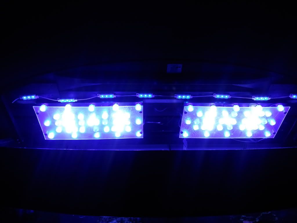
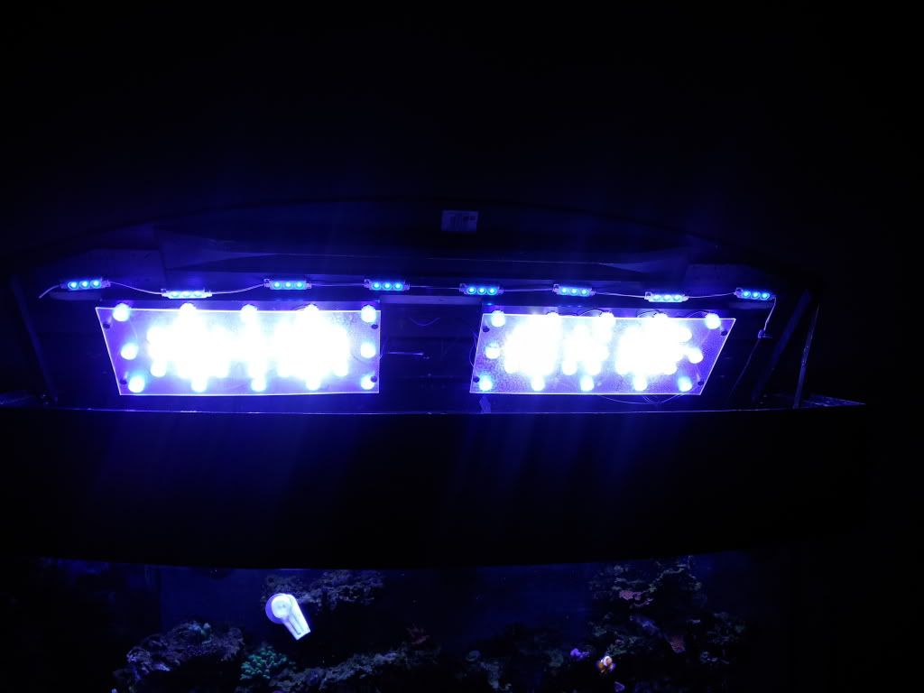
I'm enjoying spying on this thread..especially with Dread's controller contributions. I have a 80 DIY setup on my 90 gal bowfront....46RB, 16 4500, 8 6500, 10 10K. I know the white termp mix is unconventional, but I like it. I clustered the lights as described by evil on nr.com. They are on an apex lite controller. I am thrilled with the overall color temperature and growth of SPS. I got a number of frags from Mr. Coral and all are polyped out 24/7 and encrusting their plugs. My friend has the same frag pack under 2 x 250MH and is not getting as much growth. Only other difference is in the birds nest growth. His grows like a more transitional bird nest, while mine is more ball like with thicker branches. I am able to keep croceas on the sandbed. Like everyone else, I have decided to add another 20 for fuller coverage. I'll get some coral growth pics up soon but here is my setup.
|
|
|
|
|
02/13/2012, 02:22 PM
|
#436 |
|
Registered Member
Join Date: Oct 2011
Posts: 130
|
One other thing....purple corals appear white under this color temp...Anyone have experience with alternate colors that will make the pink shine through the actinics?
Last edited by Neurovet; 02/13/2012 at 02:30 PM. |
|
|
|
|
02/13/2012, 09:22 PM
|
#437 |
|
Registered Member
Join Date: May 2010
Location: Essex, MD
Posts: 979
|
I'm waiting to hear back from sparkfun. I firstly wanted to verify they did include the mux chip for that price, which it is, so no need to solder soic components (cheaper this way too)
I've also messaged them about the possibility of 200ma through the IC contacts. I sent their technical department a quick sketch to see if they recommend isolating it or just going directly through the chip. I honestly think the chip can take it, and I haven't had anything stick out in the datasheets to me as a 'max current through contact's' type deal. Either way, I'll see what they say first. If it's all good, parts will be on order tomorrow, and hopefully assembled by this weekend, working for real this times :-P
__________________
BRB, Goldfish on fire How much deeper would the ocean really be if sponges didn't exist? Current Tank Info: 75 gallon mixed reef tank |
|
|
|
|
02/13/2012, 10:25 PM
|
#438 | ||
|
Registered Member
Join Date: Sep 2011
Location: Schaumburg, IL.
Posts: 621
|
Quote:
Quote:
Nick
__________________
180G - 5 Yellow Tail Blue Damsels, Two Lined Sleeper Goby, Royal Gramma, Flame Angel pair, Yellow Stripe Maroon Clown, Pearlscale Butterfly, Australian Harlequin Tuskfish, Magnificent Foxface, Yellow Current Tank Info: 180G FOWLR Established 10/2010 |
||
|
|
|
|
02/13/2012, 10:55 PM
|
#439 |
|
Registered Member
Join Date: May 2010
Location: Essex, MD
Posts: 979
|
lol, no not at all. I did see 190ma at full power through the dimmer circuit, but again that's at .7v. The traces I believe really only care about current though, not voltage, so it will still be the limiting factor. I'm thinking we're still ok though as we use multiplex systems all the time in our controls, and all of our outputs are 400-500ma. Granted I've never taken one apart completely to see if it's isolated or not, but alot of the transistors I was looking at require anywhere from a 50ma-500ma signal anyways. This is newer stuff for me so I won't be surprised if I'm wrong and we do need to isolate though.
__________________
BRB, Goldfish on fire How much deeper would the ocean really be if sponges didn't exist? Current Tank Info: 75 gallon mixed reef tank |
|
|
|
|
02/14/2012, 07:10 AM
|
#440 |
|
Registered Member
Join Date: Apr 2011
Location: Dominican Republic
Posts: 556
|
Everything you say is over my head, lol, but great job.
__________________
Bigger/more tanks don't give you knowledge, they just show you have the money... ICH is overrated... Current Tank Info: Designing a 200G |
|
|
|
|
02/14/2012, 09:39 PM
|
#441 |
|
Registered Member
Join Date: Sep 2011
Location: Schaumburg, IL.
Posts: 621
|
lol. at 0.7V voltage will not be a limiting factor of the traces unless they were very very long and introduced a voltage drop. Now if we were talking in thousands of volts you could have arcing issues with traces close enough together but no, not in low voltage stuff.
I cant wait to see how this works out. Nick
__________________
180G - 5 Yellow Tail Blue Damsels, Two Lined Sleeper Goby, Royal Gramma, Flame Angel pair, Yellow Stripe Maroon Clown, Pearlscale Butterfly, Australian Harlequin Tuskfish, Magnificent Foxface, Yellow Current Tank Info: 180G FOWLR Established 10/2010 |
|
|
|
|
02/14/2012, 10:03 PM
|
#442 |
|
Registered Member
Join Date: May 2010
Location: Essex, MD
Posts: 979
|
well sparkfun hasn't gotten back to me yet on what current those boards can handle. If I do in fact need to do transistors or something I need to do some research with them. One of the problems I see is that generally the transistor would be directing current from the same overall power supply, and basically just adds it's signal to the current already flowing.
After I thought about that for a few minutes, we have 2 seperate isolated dc circuits involved. A positive current from one circuit will not flow to the ground of the other... know what I mean? That basically means the transistor never closes. However, instead of transistors we may just need to look at micro-relays, which I'm digging around into now looking at available specifications and pricing. Least the micro-relay will give us a bare set of contacts to pass the dimmer circuit through. Edit for total brain fart: Nobody said the common had to be sourced from the arduino :-P We can actually sink whatever current the transistor needs back to the negative dimmer wire by simply tapping off the negative and bringing it to the common pin of the multiplex switch
__________________
BRB, Goldfish on fire How much deeper would the ocean really be if sponges didn't exist? Current Tank Info: 75 gallon mixed reef tank Last edited by dread240; 02/14/2012 at 10:22 PM. |
|
|
|
|
02/14/2012, 10:34 PM
|
#443 | |
|
Registered Member
Join Date: May 2010
Location: Essex, MD
Posts: 979
|
Quote:
__________________
BRB, Goldfish on fire How much deeper would the ocean really be if sponges didn't exist? Current Tank Info: 75 gallon mixed reef tank |
|
|
|
|
|
02/15/2012, 08:32 AM
|
#444 |
|
Registered Member
Join Date: Nov 2011
Location: Lafayette, IN
Posts: 65
|
Just got my 90 leds in for my 75g display and 20L macro-garden. Wondering if the macro garden needs the blue LEDs or should it be a mainly white?
Waiting til today to go out and get the c-channels and angle to build the frame for the 75, still debating on if I want to do 1 4' frame or a pair of 18" frames (have about 22" between outer frame and center brace). |
|
|
|
|
02/19/2012, 05:49 PM
|
#445 |
|
Registered Member
Join Date: May 2010
Location: Essex, MD
Posts: 979
|
I haven't forgotten about you guys by any means, I've just been super busy with work and other things going on (we had our frag swap, friend had to tear down his tank, various other things). Plus my main meter had to go back to fluke for calibration (we have to calibrate them once a year or they're not allowed to be used for work).
Doing research has pointed me towards n-channel mosfets, and there are 2 options of trying to use them. One is gauranteed by using the dimmer circuit to actually trigger the mosfets, but it makes the wiring a bit trickier for the resistors (i.e. where to tap for the mosfet and how to tie it all in together) The other, which talking to a buddy of mine said will work, is that by using an arduino source to build the gate in the mosfet, the current from the dimmer circuit can flow through it as well too. With it being a seperate dc source compared to the arduino, they should just run parallel and not interfere with each other. That would make things stupid easy as for wiring, which is what I'm hoping for. I'm hoping to have it done sometime this week. If not, I think I'll take everything to MN with me when I head there for work. I'll probably have time to kill, although I can say TCMAS (Twin Cities Marine Aquaria Society) is definitely giving me some good options for keeping me occupied for the 3 weeks I'll be out there.
__________________
BRB, Goldfish on fire How much deeper would the ocean really be if sponges didn't exist? Current Tank Info: 75 gallon mixed reef tank |
|
|
|
|
02/20/2012, 11:47 AM
|
#446 |
|
Registered Member
Join Date: Aug 2011
Location: Old Lyme
Posts: 1,308
|
Looking for LED recomendations for a 90gallon - 48X18X24
Will have SPS. LPS, Zoas - basicly it all... can someone give me a brake down of what i should order from a-z.. aka which aquastyle kit + rails and such? Thanks Chris |
|
|
|
|
02/20/2012, 12:09 PM
|
#447 | |
|
Registered Member
Join Date: Oct 2009
Location: Houston TX
Posts: 1,411
|
Quote:
or go with a 72 led kit and order 5 4ft channels from speedy metals http://www.speedymetals.com/pc-2531-...-extruded.aspx why 72 over 48 like stated above? since you are using channels, you are going to need a little more to get good coverage and intensity. with heatsinks, the leds are closer together and pack a good punch. if you go with the 2 x 24 and you feel you need more light for coverage, you will have to get a smaller heatsink to fill the gap, but i doubt you will have too. for good spread try hanging the leds at diff heights. as for the drivers, you can stick with the maxwellens or upgrade to meanwells, but those will require more work in terms of wiring up. ***side note*** if you order a kit with heatsinks, ray at aquastyle will assemble the kit for you for a small fee -$10 is the last quote i got, not sure if it went up*****
__________________
Felix Nice to meet you! Current Tank Info: 60 Gallon Cube |
|
|
|
|
|
02/20/2012, 12:12 PM
|
#448 |
|
Registered Member
Join Date: Aug 2011
Location: Old Lyme
Posts: 1,308
|
thanks!
Chris |
|
|
|
|
02/20/2012, 06:42 PM
|
#449 |
|
Registered Member
Join Date: May 2009
Location: 18441
Posts: 1,531
|
Anyone else having issue now reaching Ray? I've been trying for two weeks now and havent heard back.
|
|
|
|
|
02/20/2012, 06:47 PM
|
#450 |
|
Registered Member
Join Date: Nov 2010
Location: Staten Island, NY
Posts: 181
|
Me to. Been trying for 2 weeks also with no reply.
|
|
|
|
 |
|
|
 Similar Threads
|
||||
| Thread | Thread Starter | Forum | Replies | Last Post |
| One last LED question | MrGeoReefer | Do It Yourself |
4 | 06/13/2011 01:32 PM |
| DIY led question | puck3 | Do It Yourself |
7 | 03/22/2011 10:08 AM |
| URGENT, about the nano rapid led kit. | a44007 | Lighting, Filtration & Other Equipment | 5 | 12/27/2010 01:02 AM |
| NEW LED FIXTURE COMMING, NOW WHAT? help ? | a44007 | Lighting, Filtration & Other Equipment | 6 | 12/26/2010 01:20 PM |
| One quick DIY LED question | Impossible | Do It Yourself |
4 | 10/27/2010 09:50 AM |


