
|
|
|
|||||||
 |
| Thread Tools |
 01/22/2014, 01:41 PM
|
#26 |
|
Registered Member
Join Date: Apr 2011
Posts: 31
|
kapelan,
Very nice... where can I buy one instead of building one myself? |

|

|
|
01/22/2014, 03:33 PM
|
#27 |
|
Registered Member
Join Date: Nov 2011
Location: Keighley West Yorkshire
Posts: 101
|
I have a Question please dude
If you wanted to run say a small sting of blues for moon light is this possible As when you Buy Led drivers you get 350 700 and 1000 can the drivers be changed to suite this or do you have to but the LEDs to match the drive Hope this makes sense been looking at doing LEDs For 18 months now and still do not fully 100% understand it all. But Love the challenge and i do like the design of yours  Is the code easy to play with. Thanks again Simon |
|
|
|
|
01/23/2014, 12:20 AM
|
#28 |
|
Registered Member
Join Date: May 2008
Location: Canada
Posts: 159
|
Led drivers can be adjusted.
1000mA is maximum |
|
|
|
|
01/23/2014, 12:01 PM
|
#29 |
|
Registered Member
Join Date: Nov 2011
Location: Keighley West Yorkshire
Posts: 101
|
That's Great News
|
|
|
|
|
02/08/2014, 04:17 PM
|
#30 |
|
Registered Member
Join Date: Nov 2011
Location: Keighley West Yorkshire
Posts: 101
|
any updates on this
|
|
|
|
|
02/09/2014, 12:56 AM
|
#31 | |
|
Registered Member
Join Date: Jun 2013
Posts: 86
|
Quote:
|
|
|
|
|
|
06/10/2014, 11:06 AM
|
#32 |
|
Registered Member
Join Date: May 2008
Location: Canada
Posts: 159
|
Version 2.02.
Main board includes: - timer chip - PH, ORP channels - 8 channels power block (relay) 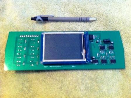 On the right side the bower block, triacs and connector which goes to power sockets: 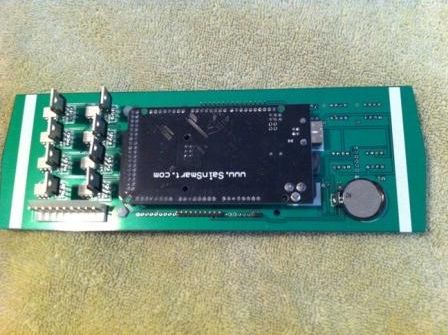 Drivers PCB, 8 drivers on the board each up to 1000mA: 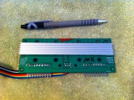
|
|
|
|
|
06/10/2014, 12:55 PM
|
#33 |
|
Premium Member
 Join Date: Nov 2006
Posts: 355
|
is there available sketch?
|
|
|
|
|
06/10/2014, 01:07 PM
|
#34 |
|
Registered Member
Join Date: May 2008
Location: Canada
Posts: 159
|
v2.02 software:
https://docs.google.com/file/d/0B42Z...84b2UzYkE/edit Now each timer has seconds. Each channel controlled by 16 timers. |
|
|
|
|
06/10/2014, 03:05 PM
|
#35 |
|
Registered Member
Join Date: Nov 2011
Location: Keighley West Yorkshire
Posts: 101
|
Nice one dude
|
|
|
|
|
06/10/2014, 03:38 PM
|
#36 |
|
Registered Member
Join Date: Nov 2013
Posts: 1
|
Congratulations. Very well done. Super clean solution. Would it be possible for you to update the BOM and support to get boards fabricated to replicate your controller? I am really expectant for it.
|
|
|
|
|
08/18/2014, 09:32 PM
|
#37 |
|
Registered Member
Join Date: May 2008
Location: Canada
Posts: 159
|
Update.
------------- Shortly about this device: - 8 fully controlled LED dimmable channels: sun/sunset/clouds/lightning storm modes. - Controlled 8 power lines - For each power line 16 timers - Each timer with second's precision - Support 4 overflow sensors - Temperature control - PH control - ORP control From the back pannel: HDMI connector - for LED drivers USB 3.0 connector - for temperature sensor and overflow sensors BNC - one for PH another for ORP probe From video the system in a cloud mode, i.e. each channel slowly fading, it looks pretty cool: controller changes color randomly (I love this function). Video: https://www.youtube.com/watch?v=YFApA5dDBCY https://www.youtube.com/watch?v=oM0R_-g3tZs#t=206 https://www.youtube.com/watch?v=zFKk92H_HR8 https://www.youtube.com/watch?v=IV4M...ature=youtu.be -- Now it looks like this: 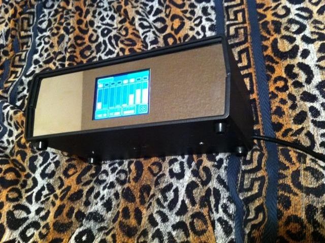 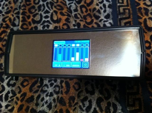 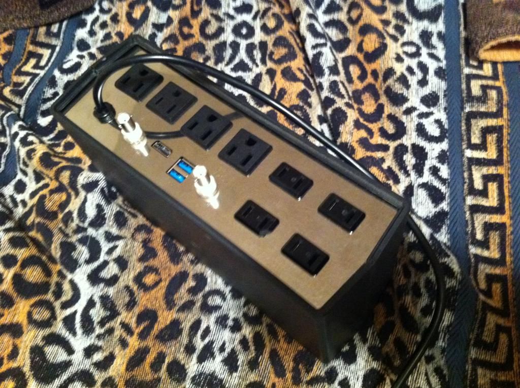 Software v2.03: https://drive.google.com/file/d/0B42...it?usp=sharing |
|
|
|
|
09/01/2014, 11:13 AM
|
#38 |
|
Registered Member
Join Date: May 2008
Location: Canada
Posts: 159
|
|
|
|
|
|
11/16/2014, 10:45 AM
|
#39 |
|
Registered Member
Join Date: May 2008
Location: Canada
Posts: 159
|
|
|
|
|
|
11/26/2014, 10:23 AM
|
#40 |
|
Registered Member
Join Date: Nov 2014
Posts: 12
|
Hi Kapelan i really like your controller where i can find the wiring/operating instructions, i.e pin outs for led channels etc. I was also wondering if it can be adapted to be used with meanwell LDD drivers as i have these already.
I was going to use the Stilo 3.0 but after months of frustration with coding /compiling errors (newby to Arduino) i got the code to compile but my display keeps refreshing every 2 seconds and i can,t solve it despite following posts with the same problems i finally gave up on it. Your upload worked straight away and is displaying on my screen, but i cant find the operation/wiring instructions. Thank you. |
|
|
|
|
11/27/2014, 10:10 AM
|
#41 |
|
Registered Member
Join Date: Nov 2014
Posts: 12
|
Can anyone help me on this , as this thread seems to be dead.
I do not seem to be able to find documentation on this controller i.e. what each pin of the arduino controls what function led channel etc. , is it available. .Newby help !!!!. |
|
|
|
|
11/27/2014, 08:34 PM
|
#42 |
|
Registered Member
Join Date: May 2008
Location: Canada
Posts: 159
|
One wire bus for temperature sensor DS1820: A3
Timer DS1307 rtc( 42,43) LED pins: 13,12,11,10,9,8,44,45 Cooler for LED: 46 PH: A1 ORP: A0 Power lines: A8,A9,A10,A11,A12,A13,A14,A15 To contact sensors (overflow): A4,A5,A6,A7 |
|
|
|
|
11/28/2014, 11:09 AM
|
#43 |
|
Registered Member
Join Date: Nov 2014
Posts: 12
|
Hi Kapelan
Thank you very much for that information , i am going to have me some fun. Cheers. |
|
|
|
|
12/04/2014, 07:44 AM
|
#44 |
|
Registered Member
Join Date: May 2008
Location: Canada
Posts: 159
|
LED set up
That's kind of innovation.
LED levels are configured as a chart now: just point the desired level on the screen. The system will create a chart and all related timers. 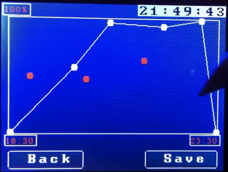 nice and easy 
|
|
|
|
|
12/09/2014, 09:32 AM
|
#45 |
|
Registered Member
Join Date: May 2008
Location: Canada
Posts: 159
|
new design
I'm thinking about a new design:
Create a PCB: all in one. I.e. we actualy do not need a shield between Arduino and TFT screen. So it would make sense to create a new arduino to which TFT attached directly. I mean it would be the same chip, all compatible to Mega2560, that should work with touch screen without any other PCB. So assembled device will have only 2 parts: - a new PCB, which is equivalent to Arduino+TFT shield - touch screen. Anybody would be interesting? |
|
|
|
|
12/13/2014, 02:47 PM
|
#46 | |
|
Registered Member
Join Date: Nov 2014
Posts: 12
|
led output
Quote:
|
|
|
|
|
|
12/13/2014, 02:52 PM
|
#47 |
|
Registered Member
Join Date: Nov 2014
Posts: 12
|
Hi Kapelan is the new led level screen that you posted 44 available in version 4 of your code , or do I have to download another updated version.
|
|
|
|
|
12/17/2014, 07:50 AM
|
#48 | |
|
Registered Member
Join Date: May 2008
Location: Canada
Posts: 159
|
Quote:
|
|
|
|
|
|
12/17/2014, 02:28 PM
|
#49 | |
|
Registered Member
Join Date: Sep 2014
Location: Cleveland, OH
Posts: 4
|
Quote:
This is only 2.7" x 4", has 6 PWM ports, 2 x 16 AMP SSR controlled AC outputs, a DS3231 RTC, 2 ports for float switches and on board 115 AC to 5V DC conversion. 1 AC plug (no wall warts) drives it all. This can control anything from LED strings to metal halide lights, dosers, pumps, etc. Working on a version that has 24 pin sockets for Meanwell LDD drivers on board. That one will be controlled off a DC power supply similar to what you've done. All one board though. |
|
|
|
|
|
01/12/2015, 02:24 PM
|
#50 |
|
Registered Member
Join Date: May 2008
Location: Canada
Posts: 159
|
v.2.05 update: https://drive.google.com/folderview?...kU&usp=sharing
1. Added Chiller. One sensor can control chiller and heater. From touch screen we configure Area of Comfort. If the temperature greater then Alarm Level – chiller turn ON. If less than some level - turn on the heater. 2. Added support for up to 4 temperature sensors. |
|
|
|
|
| Tags |
| aquarium controller, arduino, led, led controller |
|
|


