
|
|
 12/05/2013, 01:43 PM
|
#1 |
|
Registered Member
Join Date: Jul 2013
Location: Sweden
Posts: 58
|
DIY LED questions, Typhon
Hi all DIY enthusiasts out there
 Im planning on building a new LED fixture for my approx. 40gallon reef. (60cm*40cm*60cm). Im not very satisfied with the one I have now.. I like projects like this but my knowledge with electrics are not that good. Therefor do I ask you for some help and advice I would like to be able to control the lights with dimming functions like the ones a Typhon PWM controller provides. But Im not to sure how to wire it all together with drivers and so on.. I would like a slick and easy setup Link to the Typhon --> http://stevesleds.com/uploads/Typhon_LED_Controller.pdf http://shop.stevesleds.com/Typhon-Ty...ler-Typhon.htm This might be a idiotic idea but Ill ask anyway, how should I learn otherwise?  Will I be able to connect the Typhon via one of these http://www.aquastyleonline.com/produ...tion-wire.html to four of these connected to each-other http://www.aquastyleonline.com/produ...ing-Board.html powered by one of these http://www.aquastyleonline.com/produ...50%252d48.html ? I would then just put the drivers in a project-box with a small fan and it would not be too much of a mess. Thanx
|

|

|
|
12/05/2013, 06:27 PM
|
#2 |
|
Registered Member
Join Date: Sep 2003
Location: North Carolina
Posts: 20,050
|
The answer to your question is "maybe" (probably)..But without knowing the exact number you plan to use and specs of the LED's (max forward voltage and max current) you intend to use, we can't say yes..
In general it works like this.. -You will put all LED's in series (google it if you don't understand) Parallel strings should be avoided. -The driver should have a current rating at or below the max current rating of the lowest rated LED in the series string. -The power supply output voltage must be greater than the sum of all the LED's max forward voltage rating in that series string. (example.. 5 leds in series with a 3v forward voltage means your power supply must be greater than 5 x 3 = 15V) -LEDs require sufficient heatsinking
__________________
Who me? |
|
|
|
|
12/06/2013, 02:22 AM
|
#3 |
|
Registered Member
Join Date: Jul 2013
Location: Sweden
Posts: 58
|
Thanx! Sorry for not specifying more
I have some knowledge about DIY projects like this because I have built a LED fixture before. Very simple though.. The main question of mine is if the Typhon will work with the drivers from aquastyle? The drivers have four pairs of pins for PWM and the Typhon have four pairs of pins for PWM. On each driver you can choose which channel it will operate. I think it will work like this; if you chose the first driver to operate channel one then the PWM signal from channel one from the controller will be used on that driver. The other three PWM signals will just "travel through" to the next driver. I will post more specifics about LEDs later. To be honest, I have not made up my mind yet on which LEDs I will be using. I think I will use 5x10w multichips (1000mA) and 16 or so 3w single LEDs (1000mA). |
|
|
|
|
12/06/2013, 04:19 AM
|
#4 |
|
Registered Member
Join Date: Jun 2010
Posts: 295
|
Slick and easy: I just redid my DIY LEDs with Makers LED drivers and two of their controllers.
|
|
|
|
|
12/06/2013, 07:31 AM
|
#5 |
|
Registered Member
Join Date: Jul 2013
Location: Sweden
Posts: 58
|
Yea, that's one way to do it
If I go with the Typhon and four driverboards, then I'll place it all in a black projectbox and cut a hole for the display and a small fan |
|
|
|
|
12/06/2013, 07:43 AM
|
#6 |
|
Registered Member
Join Date: Sep 2003
Location: North Carolina
Posts: 20,050
|
Yes the products you listed in your first post should all work just fine together.
__________________
Who me? |
|
|
|
|
12/06/2013, 07:55 AM
|
#7 |
|
Registered Member
Join Date: Jul 2013
Location: Sweden
Posts: 58
|
Thank you mcgyvr!

|
|
|
|
|
12/27/2013, 03:59 PM
|
#8 |
|
Registered Member
Join Date: Jul 2013
Location: Sweden
Posts: 58
|
So, I have now got my drivers and power supply, just waiting for my typhon an some LEDs. Just facing a problem though..
On the typhon I know which PWM-pins are negative and which are positive but on the driverboards I dont. If I connect (accidentally) the negative PWM from the typhon to the positive PWM on the driverboards, how will this affect? Will de drivers or typhon be damaged? |
|
|
|
|
12/27/2013, 04:05 PM
|
#9 |
|
Registered Member
Join Date: Sep 2003
Location: North Carolina
Posts: 20,050
|
There is more than likely a + or - marked on the circuit board..
__________________
Who me? |
|
|
|
|
12/27/2013, 04:11 PM
|
#10 |
|
Registered Member
Join Date: Jul 2013
Location: Sweden
Posts: 58
|
This is what it looks like..
On the left PWM input, on the right PWM output to next driverboard. With the red thing you controll which channel the driver will opperate There are 8 pins on each side, well 8pins on the left side and 8female connectors on the right side 
|
|
|
|
|
12/28/2013, 03:45 AM
|
#11 |
|
Registered Member
Join Date: Jul 2013
Location: Sweden
Posts: 58
|
Somebody?
|
|
|
|
|
12/28/2013, 10:11 AM
|
#12 |
|
Registered Member
Join Date: Oct 2009
Location: Houston TX
Posts: 1,411
|
The way I see it, that board was designed to work with their dimmer, the solarlux.
So I don't think those pins with the jumpers will matter for the typhon, I could be wrong. Now, for your question, I think the pins on the right are all one connection, could be - or + Just have to email ray and ask him, to be certain, I think that's your best option. That or get a meter out and do some testing.
__________________
Felix Nice to meet you! Current Tank Info: 60 Gallon Cube |
|
|
|
|
12/28/2013, 10:23 AM
|
#13 |
|
Registered Member
Join Date: Jul 2013
Location: Sweden
Posts: 58
|
Yes, I actually did email him today and asked
When I bought them I believed there was a marking on the board, I should have checked it up to be certain.. I bought them because there would be less wiring and soldering with the connections on the boards, might just been a stupid choice.. If it won't work I guess I'll have to somehow take off the drivers from the boards |
|
|
|
|
12/28/2013, 10:40 AM
|
#14 |
|
Registered Member
Join Date: Sep 2003
Location: North Carolina
Posts: 20,050
|
Just follow the traces on the circuit board.. Even with the black soldermask you should be easily able to see which pin goes where..
__________________
Who me? |
|
|
|
|
12/28/2013, 11:09 AM
|
#15 |
|
Registered Member
Join Date: Jul 2013
Location: Sweden
Posts: 58
|
I'll do that and see what I can find out
|
|
|
|
|
12/28/2013, 12:58 PM
|
#16 |
|
Registered Member
Join Date: Jul 2013
Location: Sweden
Posts: 58
|
I think I got it now..
(please check and seeif I'm right..) This is what it looks like if you follow the barely visible markings on the boards The "DIM"/dimming from the driver goes to each of the six "channel pins" on top, so you need the red jumper because otherwise the "DIM" won't be connected to the controller. One signal from the controller enters the first upper pin on the left side, this will control the first channel if you place the red jumper over channel one. The signal also travels through to the first upper pin on the right side. (probably if you want several drivers to be connected to the same channel) The first lower pin on the left side also receives a signal, this signal will control channel two. (if the jumper is set over channel two) This signal also travels through to the next driver if there are one. The second upper pin on the left side controls channel three. (if the jumper is set over channel three) Same here, the signal travels through to the next driver if there are one. The second lower pin on the left side controls channel four. (if the jumper is set over channel four). Same here, the signal travels through to the next driver if there are one. The third upper pin on the left side controls channel five. (if the jumper is set over channel five). Signal is able to travel through. The third lower pin on the left side controls channel six. (if the jumper is set over channel six). Signal is able to travel through. On aquastyleonline it says that channel five and six is just for on/off function. I'll just use four channels from the Typhon (maximum) I had do draw it like I did because I ran out of space on the paper. The "wires" that goes outside of the paper on the left side is connected to the wires that goes outside of the paper on the right side 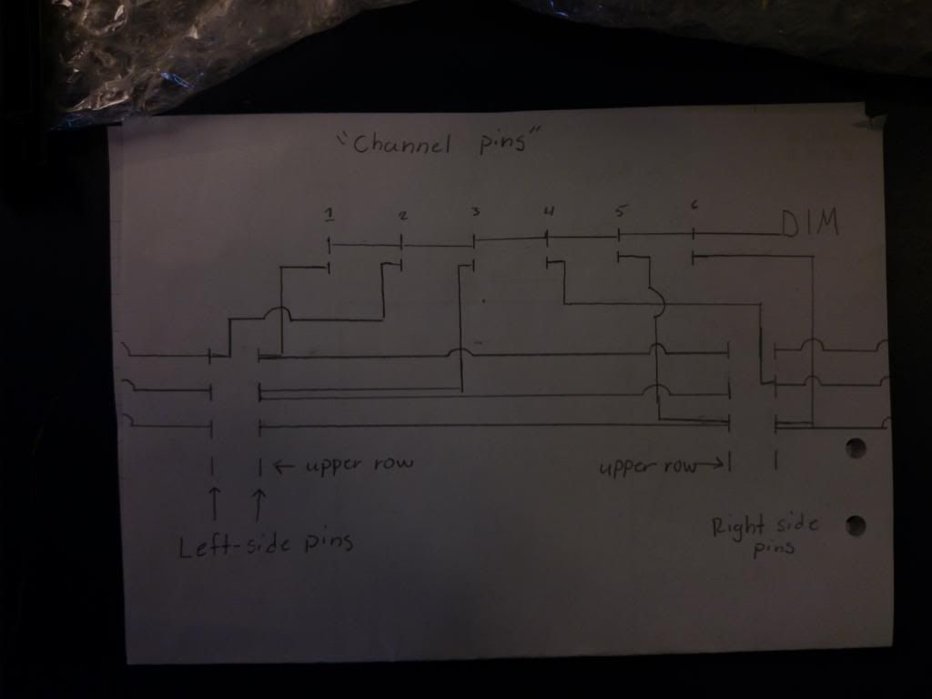 I was not able to see any markings running from the last pair of pins. Maybe these are connected to the negative input pins on the driver? The positive signals from the Typhon goes to the DIM. If you read post #8 in this thread he explains a bit about the ldd-h drivers. And that's why I think it works like this --> http://www.ultimatereef.net/forums/s...d.php?t=597399Thank you very much for your help, I was a bit foolish when I didn't check up on the specifics on the driver boards before I bought them. It all feels a bit awkward to be honest with you 
|
|
|
|
 |
| Thread Tools | |
|
|


