
|
|
|
|||||||
 |
| Thread Tools |
 06/19/2017, 07:20 AM
|
#451 |
|
Registered Member
Join Date: May 2004
Location: Dallas, TX
Posts: 11,033
|
How much power can the board handle?
Why 15 kHz? Is it the pulse timing for the commutation that's driving the resolution?
__________________
Failure isn't an option It's a requirement. 660g 380inwall+280smp/surge S/L/Soft/Maxima/RBTA/Clown/Chromis/Anthias/Tang/Mandarin/Jawfish/Goby/Wrasse/D'back. DIY 12' Skimmer ActuatedSurge ConcreteScape |

|

|
|
06/19/2017, 11:49 AM
|
#452 |
|
100-mile-commuter
Join Date: Dec 2004
Location: almost nevada
Posts: 4,721
|
Based on current evidence, the FET drivers could handle the large DCT-15000 pump, however the currently installed current shunt limits the current and that pump caps out before it gets anywhere close to 100W average.
The DCT-4000 and 6000 run at their rated power. Of course you can already buy a controller for Apex-to-DCT (would love a teardown), but this is at least pretty universal for sensorless motors. The PWM signal is effectively coupled directly to the FET drive, so if your frequency is too low you'll have your drive off for most of a phase, hence it will rapidly stall the motor. One quirk is the controller still sees BEMF and thinks its running when the rotor is stalled - there is some nasty EMI flying around here likely contributing to this.
__________________
Custom electronics purveyor. blueAcro.com Current Tank Info: 90g SPS+mixed reef (10 yrs): LEDBrick LEDs, 40g custom sump, Ca reactor, chiller, Vortech, lots of custom electronics |
|
|
|
|
06/19/2017, 11:52 AM
|
#453 |
|
Registered Member
Join Date: May 2004
Location: Dallas, TX
Posts: 11,033
|
I got one of those. Want me to take it apart for pictures?
Actually, if you really want, I'll send it to you for diagnostics. As long as I get a "materials cost" build of your version when it works... LOL  I'm serious though 
__________________
Failure isn't an option It's a requirement. 660g 380inwall+280smp/surge S/L/Soft/Maxima/RBTA/Clown/Chromis/Anthias/Tang/Mandarin/Jawfish/Goby/Wrasse/D'back. DIY 12' Skimmer ActuatedSurge ConcreteScape |
|
|
|
|
06/19/2017, 12:57 PM
|
#454 | |
|
100-mile-commuter
Join Date: Dec 2004
Location: almost nevada
Posts: 4,721
|
Quote:
__________________
Custom electronics purveyor. blueAcro.com Current Tank Info: 90g SPS+mixed reef (10 yrs): LEDBrick LEDs, 40g custom sump, Ca reactor, chiller, Vortech, lots of custom electronics |
|
|
|
|
|
06/19/2017, 01:27 PM
|
#455 |
|
Registered Member
Join Date: Mar 2008
Location: sf bay area
Posts: 5,165
|
so for the fish street controller, how do you configure it to work with the different dct pumps and the cross flow? dip switch?
I figure this is to switch the current sense resistor value. I don't think the start and run sequence would be any different |
|
|
|
|
06/19/2017, 01:31 PM
|
#456 | |
|
100-mile-commuter
Join Date: Dec 2004
Location: almost nevada
Posts: 4,721
|
Quote:
__________________
Custom electronics purveyor. blueAcro.com Current Tank Info: 90g SPS+mixed reef (10 yrs): LEDBrick LEDs, 40g custom sump, Ca reactor, chiller, Vortech, lots of custom electronics |
|
|
|
|
|
06/19/2017, 02:13 PM
|
#457 | |
|
Registered Member
Join Date: May 2004
Location: Dallas, TX
Posts: 11,033
|
Quote:
__________________
Failure isn't an option It's a requirement. 660g 380inwall+280smp/surge S/L/Soft/Maxima/RBTA/Clown/Chromis/Anthias/Tang/Mandarin/Jawfish/Goby/Wrasse/D'back. DIY 12' Skimmer ActuatedSurge ConcreteScape |
|
|
|
|
|
06/19/2017, 02:14 PM
|
#458 |
|
Registered Member
Join Date: May 2004
Location: Dallas, TX
Posts: 11,033
|
I'll take pics
 Was hoping for more invasive testing that I don't have the bandwidth to do now.
__________________
Failure isn't an option It's a requirement. 660g 380inwall+280smp/surge S/L/Soft/Maxima/RBTA/Clown/Chromis/Anthias/Tang/Mandarin/Jawfish/Goby/Wrasse/D'back. DIY 12' Skimmer ActuatedSurge ConcreteScape |
|
|
|
|
06/19/2017, 03:21 PM
|
#459 |
|
100-mile-commuter
Join Date: Dec 2004
Location: almost nevada
Posts: 4,721
|
In case you're really itching to see the startup waveform:
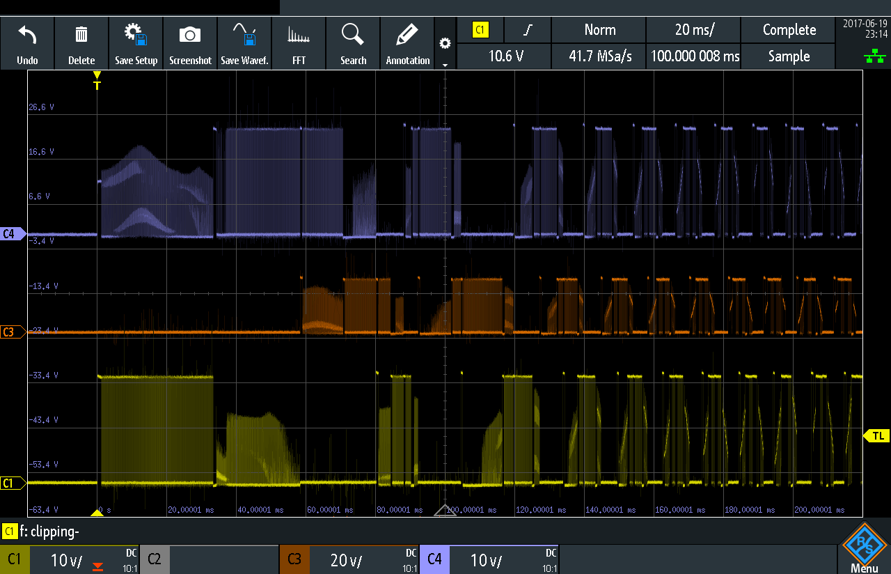 Motor is running at about 100ms in.
__________________
Custom electronics purveyor. blueAcro.com Current Tank Info: 90g SPS+mixed reef (10 yrs): LEDBrick LEDs, 40g custom sump, Ca reactor, chiller, Vortech, lots of custom electronics |
|
|
|
|
06/19/2017, 03:57 PM
|
#460 |
|
Registered Member
Join Date: May 2004
Location: Dallas, TX
Posts: 11,033
|
picture didn't make it... scratch scratch
__________________
Failure isn't an option It's a requirement. 660g 380inwall+280smp/surge S/L/Soft/Maxima/RBTA/Clown/Chromis/Anthias/Tang/Mandarin/Jawfish/Goby/Wrasse/D'back. DIY 12' Skimmer ActuatedSurge ConcreteScape |
|
|
|
|
09/12/2017, 06:46 AM
|
#461 |
|
Registered Member
Join Date: Jun 2014
Posts: 72
|
I have not been through this whole thread yet (still on the firs page) but I want to give a BIG thank you to d0ughb0y for all you do. First, a complete controller and now your sinking your teeth into this with unlimited info and shared experiments, wow! You, Karimwassef and all the other that take their time out to do these things for people like us are awesome.
Thank you, thank you thank you!! |
|
|
|
|
09/21/2017, 02:07 PM
|
#462 |
|
Registered Member
Join Date: Sep 2017
Posts: 4
|
Hello Gents,
I have the dcp series pumps and want to control them from a p4. Still scratching my head lol. Got a cp55 that the controller gave up the ghost on too so looking for something to build to replace that as nothing on the market seems to touch the cp55 or dcp series pumps to replace the original controllers ! Anyway superb work gents i watch on with interest. |
|
|
|
|
05/05/2018, 05:52 PM
|
#463 |
|
Registered Member
Join Date: May 2004
Posts: 70
|
I am bumping this thread to see if any of you guys are still working on a custom controller. After reading the thread, I'm also curious if anyone tried increasing the supply voltage to the [cheap] BLDC controllers above 24V to achieve pump outputs closer to the stock controllers.
I spent some time today comparing waveforms on my oscilloscope between this BLDC controller and the DCT and DCP controllers, and think that higher supply voltage will be necessary. Since all of the controllers use a PWM output without any feedback loop to adjust pulse width, it would be a coincidence for the fixed pulse width profile of any controller to match the power requirement of some random pump. I now realize that the controllers are designed with some target impedance, and the "high power" BLDC controllers seem to be designed specifically for high current motors (low coil resistance). What I've found is that the controller linked above, which supports up to 36V, is able to achieve a little more than half of the rated flow at about half of the power draw of the stock controller. However, at the lowest speeds (and zero head pressure), it matches the stock controller. It isn't until it crosses a threshold that the speed and power draw drops in half. Near that threshold, the pump makes a significant amount of noise, and the power draw bounces up and down. The highest power draw I'm able to achieve with my Jebao DCP-15000 is 56W with the cheap BLDC controller, then it gets noisy and unstable. However, I suspect that increasing the supply voltage beyond 24V would help that quite a bit. With the stock controller it goes just above 100W. I was very disappointed a few minutes ago to find that my 36V power supply is fried, so I'm going to order another one. However, I'm hoping that someone following this thread has tried increasing the voltage to overcome this issue. Last edited by gernby; 05/05/2018 at 07:05 PM. |
|
|
|
|
09/21/2018, 04:18 PM
|
#464 | |
|
Registered Member

Join Date: Jan 2009
Location: South Carolina, USA
Posts: 409
|
Quote:
Thanks
__________________
Claudio Click on my username and 'Visit jjstecchino's homepage!" to view my 180 gallon reef build thread. Current Tank Info: 180 Gallon Reef in Infancy |
|
|
|
|
|
09/22/2018, 10:58 AM
|
#465 |
|
Registered Member
Join Date: May 2004
Posts: 70
|
I'm glad this thread was bumped!
I just realized that I never reported back about how well increasing the voltage did with the variable PWM controller! It turns out that each pump requires a customized voltage in order for them to operate as expected. It makes sense if you think about it... It requires a certain amount of torque to turn the impeller at a certain speed. Bigger pumps require more torque than smaller ones. Since the variable PWM controllers have a fixed PWM profile, the only way to increase or decrease torque at a particular RPM is to increase or decrease the voltage. It helped to use a Kill-A-Watt meter to monitor power consumption of the pump as I adjusted voltage, since the power reading became more stable and closer to the pump's power spec as I increased the supply voltage. The sound and flow from the pump stabilized also. |
|
|
|
|
01/08/2019, 07:55 AM
|
#466 |
|
Registered Member
Join Date: Jun 2018
Posts: 37
|
Anyone have any luck getting their 15000's working to specs with higher input voltages?
|
|
|
|
|
08/14/2019, 09:35 AM
|
#467 |
|
Registered Member
Join Date: Sep 2010
Location: Pasadena
Posts: 36
|
I was think the same but I'm be using a raspberrypi. What I'm thinking is opening the original driver and cut off the 5v control signal line and connect it to a pca9685 (an pwm ic) of course it need to convert the digital pwm back to an 0-5v analog. The 24 power supply will also need to ground to the board.
Of course of this work you loss all the button control on the original controller. Sent from my SM-G975U using Tapatalk |
|
|
|
|
08/14/2019, 09:53 AM
|
#468 |
|
Registered Member
Join Date: Sep 2010
Location: Pasadena
Posts: 36
|
If that dont work have anyone try building the driver itself using the same ic, same capacitor a resistors and voltage regulator as the original driver board?
Sent from my SM-G975U using Tapatalk |
|
|
|
|
12/29/2019, 11:17 AM
|
#469 |
|
Registered Member
Join Date: Dec 2019
Location: Germany
Posts: 1
|
Any News about this ?
i would like to controll my flow pumps by reef pi instead of the OEM Controllers. |
|
|
|
|
01/20/2020, 09:50 PM
|
#470 |
|
Registered Member
Join Date: Oct 2011
Posts: 3
|
I've just successfully used one of these drivers to control an OW series pump with an Arduino (technically an ESP32). It's extremely simple although my W and U pins were reversed from the description. If it doesn't work, try swapping them.
Next I would like to try a DRV10983 instead to get sinusoidal control. If it goes well, I'll start a thread about it. |
|
|
|
|
|
|


