
|
|
 04/19/2012, 10:56 PM
|
#1 |
|
Registered Member
Join Date: Mar 2008
Location: sf bay area
Posts: 5,165
|
anyone built their own ph circuit?
I just did and is it normal to take a few minutes from power up to get to a stable reading? On power up I get a reading of around 6 and it takes a good 4-5 minutes before it reaches 8 where the reading settles. I don't have calibration solution right now so this is just the probe in a cup of tank water and just used calculated values based on op amp gain to get the ph.
|

|

|
|
04/27/2012, 10:25 AM
|
#2 |
|
Registered Member
Join Date: Jul 2011
Posts: 118
|
how much was the cost of the build? I found a premade sheild on ebay for $25 and have been wondering if that was about right.
The probes can be bought from china for about $8 a peice but trhe shipping is $40. You would have to buy a half dozen to come out on top. shark boy |
|
|
|
|
04/27/2012, 12:14 PM
|
#3 |
|
Registered Member
Join Date: Mar 2008
Location: sf bay area
Posts: 5,165
|
you can buy the parts for under $5, retail price.
 it does not have the serial interface though, just a direct analog line to be read by the arduino. you can get the same stamp without the serial interface for $15+ shipping elsewhere. but still, you can get the parts at retail price for under $5, I imagine it probably costs these sellers way less to make the ph stamps. the circuit itself is pretty straight forward and works fine once the reading settles. I was inquiring more from people who actually built one if they have the same result. I know the difference between $5 and $15 (or even $25) is minimal, but with premade ones, the circuits are designed to cover the entire 0-14 ph, which gives you very little resolution for your ph reading. with your own circuit, you can adjust the resistor values so your 0-5 volt will cover say 4-12ph thus giving you a better resolution on your ph reading. For reef application, you can make the range just cover 7-10, just so you can calibrate it with the standard 7 and 10 calibration fluid. That would be the main motivation to build your own rather than buy one for $25. |
|
|
|
|
04/27/2012, 01:00 PM
|
#4 |
|
Registered Member
Join Date: Apr 2012
Location: Sacramento, CA USA
Posts: 238
|
Are you going to share the circuit and parts list with us?
|
|
|
|
|
04/27/2012, 01:45 PM
|
#5 |
|
Registered Member
Join Date: Mar 2008
Location: sf bay area
Posts: 5,165
|
sure, I thought it was common knowledge
its not a highly classified secret. go to reefangel website and download the schematic for main board. I used the one from sparkey's widget http://www.sparkyswidgets.com/Projects/pHInterface.aspx I see he does not sell the version with no cpu ($15) and increased the price of the one with cpu from $25 to $30. So now the lowest ready made price would be the atlas ph stamp from amazon, which is $25 shipped. But like I said, that circuit covers the entire 0-14 ph range, thus reducing the resolution of the reading. |
|
|
|
|
04/27/2012, 01:51 PM
|
#6 |
|
Registered Member
Join Date: Jun 2011
Location: South Texas
Posts: 2,159
|
I have been planning to use the Atlas stuff, including their probes, but they are rather pricey for the kits. Do you know which probe works with the Atlas stamps? Or, which probe are you using for your home-brew stamp?
__________________
-You had me at PWM |
|
|
|
|
04/27/2012, 02:08 PM
|
#7 |
|
Registered Member
Join Date: Apr 2012
Location: Sacramento, CA USA
Posts: 238
|
Thanks! I'll check that out.
|
|
|
|
|
04/30/2012, 01:51 AM
|
#8 |
|
Registered Member
Join Date: Mar 2012
Location: Colorado
Posts: 10
|
It always makes me glad to see a people finding my tutorial useful! Are you using the fixed gain or the adjustable one? Depending on the component values used and if an rc filter was included it could take a little bit to settle but 6 minutes seems a bit long.
I am in the middle of getting a new analog out design up and will be quite a bit cheaper. The newer USB design is really meant as a "controller" or remote unit. I have some older designs with the 328p foot print on them, if anyone wants a PCB let me know I ship em out! Also if anyone needs help with this stuff let me know, I've had my share of design and trouble shooting hehe. |
|
|
|
|
04/30/2012, 09:40 AM
|
#9 |
|
Registered Member
Join Date: Mar 2008
Location: sf bay area
Posts: 5,165
|
thanks sparky. your project page was helpful. I am currently using fixed circuit. I simply followed the calculations for the gain and offset to change the resistor values (actually, my offset right now is right at center, 2.5v).
If I calculate the circuit to cover ph 5 to 12 only, any value outside of that will just cause the signal to clip right? I wanted to make one step of the analog read to be equivalent to 0.01ph, or maybe even two steps. It would be cool if you include the feature to allow setting the range (adjusting offset and gain) to your new analog design, as not all applications would need the entire 0-14 range. To make the settling time faster, should I just use a smaller resistor value combination? Like if I need a gain of 7.6 on the first stage, instead of 220k and 33k, I can use 20k and 3k? what is the effect of using a higher or lower resistor value on the RC filter to the circuit? if I have to wire the bnc connector to the circuit board, do I need to use a coax cable? or just plain wire will work? wire length would be 3-4 inches. thanks Last edited by d0ughb0y; 04/30/2012 at 09:50 AM. |
|
|
|
|
05/02/2012, 12:31 AM
|
#10 |
|
Registered Member
Join Date: Mar 2012
Location: Colorado
Posts: 10
|
Glad to hear! Which amp did you go with by chance?
Yeap that will work, you can also trim the gain down and switch to a lower ADC reference. When you pair that with oversampling and decimation you can come up with some really narrow step values, although the noise starts to show up more and more. Some tuned filters can help but will affect circuit reaction time. As for the resistors that range is what I generally use(200k), high for less power consumption but increased noise, lower for increased power consumption. When paired with capacitor to make an RC filter the resistor just limits the current, thereby slowing charge discharge rate of the cap. This is how you tune it to catch frequencies. As for wiring to the PCB, I like to keep that as short as possible with proper shielding, since its a weak signal with high impedance its quite suspetable to noise which could through readings off. This is why I tend to mount the BNC as close to the amps inputs as possible. anyways off to bed, hope that helps a bit. |
|
|
|
|
05/02/2012, 11:18 AM
|
#11 |
|
Registered Member
Join Date: Mar 2008
Location: sf bay area
Posts: 5,165
|
thanks for the tips.
I notice in your usb version you removed all capacitors except the first op-amp. what's the reason for the removal? I like fewer components. 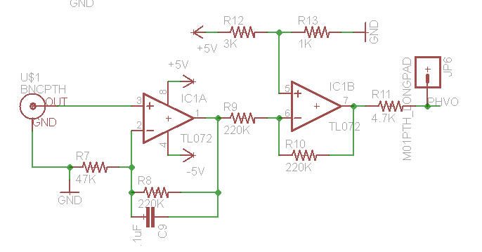 The RC forms a low pass circuit right? If I calculate f= 1/(2*PI*R*C) from the above values, I get about 7hz. I think in the original circuit values it comes to under 2 hz. I'll play around with the RC values. I ordered more capacitors and a 250k and 5k cermet potentiometer to make the gain and voltage divider adjustable. I'll be soldering the BNC to the circuit board since I have space for it now after I rearranged my layout. I'll make the input pin right next to the op amp input. Thanks |
|
|
|
|
11/04/2012, 01:38 AM
|
#12 |
|
Registered Member
Join Date: Oct 2012
Posts: 2
|
hi i have atlas pH stamp, arduino duemilanove.
i want to trigger some LEDs, buzzer,when certain pH is reached. i also want to display the pH reading on LCD display. please help me with the code. any reference would also be really helpful. this is my first time doing such project. thanks |
|
|
|
|
11/05/2012, 09:33 AM
|
#13 | |
|
Registered Member
Join Date: Jun 2011
Location: South Texas
Posts: 2,159
|
Quote:
__________________
-You had me at PWM |
|
|
|
|
|
09/10/2013, 01:18 AM
|
#14 |
|
Registered Member
Join Date: Mar 2008
Location: sf bay area
Posts: 5,165
|
I ended up desoldering and removing the sparky's ph circuit and used an atlas ph circuit. the stability difference is like night and day. I'm sure sparky's circuit works fine stand alone, but I find it unstable when connected to the rest of my circuit. (the voltage divider in the circuit is affected, and the reading changes if voltage fluctuates a tiny bit, just too many issues).
|
|
|
|
|
09/10/2013, 08:56 AM
|
#15 |
|
Registered Member
Join Date: Jun 2011
Location: South Texas
Posts: 2,159
|
I ended up with an atlas stamp and probe, although I also have a reef angel with probe. I have yet to set them up though. :/
__________________
-You had me at PWM |
|
|
|
 |
| Thread Tools | |
|
|


