|
|
|
|||||||
 |
| Thread Tools |
 06/22/2015, 01:40 PM
|
#101 |
|
Registered Member
Join Date: May 2008
Location: Canada
Posts: 159
|
I'm using this one:

|

|

|
|
06/22/2015, 01:45 PM
|
#102 |
|
Registered Member
Join Date: Sep 2013
Posts: 18
|
 Sorry that was the one I was sent this is mine and sorry for the bad drawing |
|
|
|
|
06/22/2015, 01:46 PM
|
#103 |
|
Registered Member
Join Date: Sep 2013
Posts: 18
|
 That's the thing put together |
|
|
|
|
06/22/2015, 02:43 PM
|
#104 |
|
Registered Member
Join Date: May 2008
Location: Canada
Posts: 159
|
Transistor can be opened or closed.
So, from your circuit, if a power supply provides 40V and 5A you will burn out any LED immediately. Driver guaranteed 1A to the LED. |
|
|
|
|
06/22/2015, 02:52 PM
|
#105 |
|
Registered Member
Join Date: Sep 2013
Posts: 18
|
I'm only running 22v and they have been running for 3 months
|
|
|
|
|
08/31/2015, 07:40 PM
|
#106 |
|
Registered Member
Join Date: May 2008
Location: Canada
Posts: 159
|
Raspberry PI coming
That's design for the device with web access:
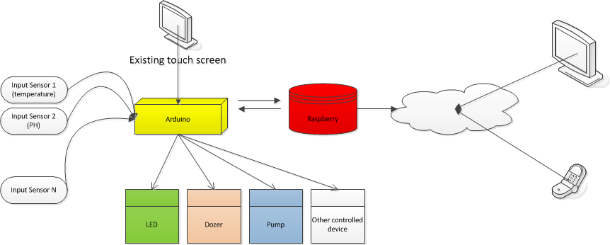 Raspberry is optional. Device is working fine without Raspberry PI. Raspberry is used as a log server and provide remote access to the device. So from somewhere on vacation we have 100% access including monitoring and control. Failure safe: in case of Raspberry die - device still working as configured |
|
|
|
|
09/03/2015, 01:43 PM
|
#107 |
|
Registered Member
Join Date: Sep 2015
Posts: 1
|
Hey
I have a question that followed the display and how to have connected? |
|
|
|
|
09/07/2015, 06:09 PM
|
#108 | |
|
Registered Member
Join Date: May 2008
Location: Canada
Posts: 159
|
Quote:
|
|
|
|
|
|
10/18/2015, 04:41 PM
|
#109 |
|
Registered Member
Join Date: Nov 2014
Posts: 12
|
Hi Kapelan,
I have some buzzer modules I would like to add to the overflow sensors what pins would I have connect them to give me an audible alarm for high and low level water in the aquarium and my sump.: |
|
|
|
|
10/19/2015, 05:30 AM
|
#110 |
|
Registered Member
Join Date: Oct 2015
Posts: 4
|
you also hand made the driver's to right?
  
|
|
|
|
|
10/19/2015, 11:23 AM
|
#111 | |
|
Registered Member
Join Date: May 2008
Location: Canada
Posts: 159
|
Pinout
Quote:
One wire bus for temperature sensor DS1820 (support up to 4): A3 Timer DS1307 rtc( 42,43) LED pins: 13,12,11,10,9,8,44,45 Cooler for LED: 46 PH: A1 ORP: A0 Power lines: A8,A9,A10,A11,A12,A13,A14,A15 Overflow sensors: A4,A5,A6,A7 Last edited by kapelan; 10/19/2015 at 11:31 AM. |
|
|
|
|
|
10/19/2015, 11:27 AM
|
#112 | |
|
Registered Member
Join Date: May 2008
Location: Canada
Posts: 159
|
Quote:
Each of them up to 1000mA. 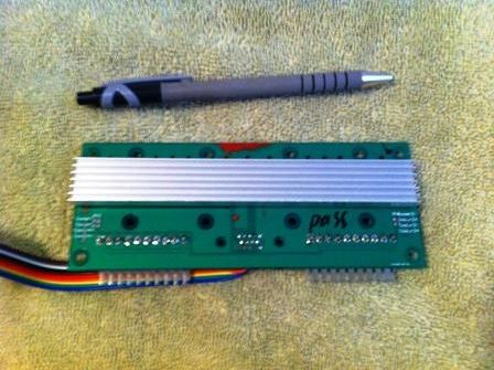
|
|
|
|
|
|
10/20/2015, 09:13 AM
|
#113 | |
|
Registered Member
Join Date: Nov 2014
Posts: 12
|
Quote:
|
|
|
|
|
|
01/30/2016, 07:47 PM
|
#114 |
|
Registered Member
Join Date: May 2008
Location: Canada
Posts: 159
|
v2.11
__________________
my tank online: http://ledacik.com |
|
|
|
|
02/06/2016, 06:41 PM
|
#115 |
|
Registered Member
Join Date: Jan 2015
Posts: 50
|
Hi kapelan
Thank you so much for this great thread I really do know how to thank you about it Its a good thing to share that work with friends here .. So as I am so noob to electronics but I take a decision to diy my led system and controller I already bought arduino mega2560 rev3 from here http://mobile.ram-e-shop.com/cat/mob...oducts_id/2147 And also the rtc http://mobile.ram-e-shop.com/cat/mob...oducts_id/2975 And the TFT LCD http://mobile.ram-e-shop.com/cat/mob...oducts_id/2699 The TFT is the most expensive part by the way I also ordered the odd drivers with PCB from here 5UP Ldd-700H Meanwell Driver on PCB + Dimmer control for Lumia 5.1 100W LEDs http://s.aliexpress.com/qYniYJf2 Anyway if I get this items above connected somehow that I really do know yet how to connect them and uploaded your software gonna work and I can control with the LCD screen above also how to get the fan cooler for heat think to be run only at certain intensity and not running in low dimming levels and how to connect it ... Thank you again and if you could help I really be thankful |
|
|
|
|
02/08/2016, 08:23 AM
|
#116 |
|
Registered Member
Join Date: May 2008
Location: Canada
Posts: 159
|
it was created for 3.2"TFT, I'm afraid you will have a trouble with 5" display.

__________________
my tank online: http://ledacik.com |
|
|
|
|
02/08/2016, 10:31 AM
|
#117 |
|
Head zoo keeper
Join Date: Nov 2005
Location: Toledo ,Ohio
Posts: 710
|
@Kapelan where did you get the case for your controller I like that style of box can you tell me the size you have also?
|
|
|
|
|
02/09/2016, 08:44 AM
|
#118 | |
|
Registered Member
Join Date: Jan 2015
Posts: 50
|
Quote:
|
|
|
|
|
|
02/09/2016, 10:03 AM
|
#119 |
|
Registered Member
Join Date: May 2008
Location: Canada
Posts: 159
|
__________________
my tank online: http://ledacik.com |
|
|
|
|
02/11/2016, 12:33 AM
|
#120 |
|
Registered Member
Join Date: Jan 2015
Posts: 50
|
[QUOTE=kapelan;24316257]http://www.aliexpress.com/item/SainS...a-84d6c40dd559[/QUOthat
Thank you very much for that but is it require rtc ? I don't see a built in rtc on shield |
|
|
|
|
08/16/2016, 08:43 PM
|
#121 | |
|
Registered Member
Join Date: Jan 2015
Posts: 50
|
Quote:
|
|
|
|
|
|
08/16/2016, 11:57 PM
|
#122 | |
|
Registered Member
Join Date: May 2008
Location: Canada
Posts: 159
|
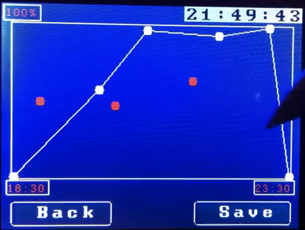
Quote:
Then press save it will open this screen. Also in order to open this screen this timer must be valid, like 5 to 10 pm. (Over midnight this screen does not work) https://drive.google.com/drive/folde...ktMcGNfR0E4QkU
__________________
my tank online: http://ledacik.com |
|
|
|
|
|
08/18/2016, 09:23 PM
|
#123 | ||
|
Registered Member
Join Date: Jan 2015
Posts: 50
|
Quote:
Quote:
also i want to tell SSD1289IC has been discontinued for many years, has been unable to continue production, with immediate effect, 3.2-inch screen has been updated to ILI9341 drive, the same hardware structure and interface definitions, driver changes slightly, the quality is more stable. could you update the tft screen lib ? |
||
|
|
|
|
08/19/2016, 01:02 PM
|
#124 | |
|
Registered Member
Join Date: May 2008
Location: Canada
Posts: 159
|
Quote:
Controller never exeed these values. "Set Color" - will display color on the tauch screen for your leds. Sunrize/Sunset with any duration can be set it up manually from the screen you posted above. Not sure what you mean under night mode. In my "night mode" I have 2 timers: one blue led about 10% before midnigh and another royal blue about 5% after midnight. The interface is very simple, please play with it a bit - it's unbreakable.
__________________
my tank online: http://ledacik.com |
|
|
|
|
|
08/19/2016, 04:46 PM
|
#125 | |
|
Registered Member
Join Date: Jan 2015
Posts: 50
|
Quote:
3.2-inch screen has been updated to ILI9341 drive working with no shield could you please take a look on it ? |
|
|
|
|
|
| Tags |
| aquarium controller, arduino, led, led controller |
|
|