
|
|
 05/04/2017, 07:16 PM
|
#9376 |
|
Registered Member
Join Date: Nov 2013
Location: Baton Rouge
Posts: 1,410
|
If u want to go with a c2c box then u can use the lower hole as the emergency drain, so it will have a elbow facing up. It doesn't look to be but about 1" below the other hole, so if u use it as the emergency u probably won't even have to make the box any deeper then normal to accommodate it.
I don't think I would use it for a return because u would have to rely on locline to not have a bunch of water drain down when it's powered off. If the locline gets pushed down for some reason it may cause u to have a flood. If u have a really big sump with a lot of extra room then it may not matter. U can eighther go a full c2c & use it as the emergency & go over the back with the return or u can go with the internal wier & exterior box & use it as one of the pass through holes. I know uncle isn't a fan of that setup & he is more knowledgeable then I am, but I like the synergy style boxes. I just don't like the sizes they make them in. I like to have as long of a wier as possible on the inside of the tank & a bigger exterior box then what they make. One of the things I like about this setup other then the space I save is u can use black acrylic for the internal box & have the bulkheads hold it on the tank, Then do a glass exterior box. I really like the look of the black acrylic. I don't know if it would be worth the extra work just to save 1.5" in the tank, but I wanted a acrylic box so between the two it was worth it to me. As far as the returns, if u don't want to go over the back of the tank then from the looks of it u have enough room between the edge of the tank & the existing holes to drill another hole for your returns. If u did it this way then u could have a longer internal box. U can make the internal box to where it covers your existing holes & still have room for returns on the ends as long as u have around 6" from the edge of the tank to where your existing hole starts. Last edited by Lsufan; 05/04/2017 at 07:21 PM. |

|

|
|
05/05/2017, 09:07 AM
|
#9377 |
|
Registered Member
Join Date: Apr 2017
Posts: 16
|
Thank-you for your responses. All very helpful. #1 thing learned, do not use the existing lower hole for return. Just asking for trouble.
I'm leaning towards going with an internal box. Question about your acrylic wier though for your external design. Don't you still have to make sure there are no leaks in the internal weir (otherwise the tank would drain to the level of the lowest leak higher than your holes with a power loss, wouldn't it?)? If so, how would you guarantee that with acrylic? Question on hole size. The current hole size is 2" diameter and they had schedule 40 1" bulkheads installed. 2" seems big to me for that but seems to have worked before. Am I asking for trouble if I continue to use a schedule 40 1" bulkhead? It seems like the only other option would be to move to schedule 80 1", but that seems like overkill. I'm assuming if I drill 2 more holes I can make them smaller and put the same size bulkheads in. BTW I'm using a 20 Gallon fishtank for the sump. So I don't have huge overflow space there but with the proper design I believe it should be enough. Thanks again, Ron |
|
|
|
|
05/09/2017, 07:57 AM
|
#9378 |
|
Registered Member
 Join Date: Dec 2009
Posts: 296
|
Running a manifold off the siphon
I have a 60g cube with an overflow box from Exotic Marine Systems. It's similar to the Ghost overflow. I reduce the siphon to 3/4" and the open channel and emergency at 1". My sump is high on a shelf in my basement giving about 7 feet drop from the water surface. Siphon starts quickly, reliably and without any trouble. It takes less than a minute. Water fills to the emergency drain. After about the 10 seconds the siphon starts and pulls water down below the open channel. Then the water gradually rises back up to the open channel.
I'm considering putting a manifold on the siphon to run two Avast Marine reactors, a small spyglass reactor with very minimal flow and one of their small sized standard regular reactors running biopellets. The flow through the biopellets needs to be a bit more substantial. I'm wondering if the manifold will create problems for system startup. All help is greatly appreciated! Thanks.
__________________
Solana Started 2/21/2010 |
|
|
|
|
05/09/2017, 12:51 PM
|
#9379 | |
|
Registered Member
Join Date: Jul 2004
Location: AWOL
Posts: 12,013
|
Quote:
Yes it will create problems for the startup. All three standpipes must be discrete, and go directly to the sump. Do not pass go, do not collect $200. If needing to feed "reactors" feed them from a tee in the return line, or run them on a separate pump... or simply eliminate them from the system altogether, considering the choice of reactors you have made.
__________________
"Things should be made as simple as possible, but not simpler." (oft attributed to Einstein; most likely paraphrasing by Roger Sessions; compactly articulates the principle of Occam's Razor) Current Tank Info: 325 6' wide Reef |
|
|
|
|
|
05/09/2017, 02:31 PM
|
#9380 | |
|
Registered Member
Join Date: Dec 2009
Posts: 296
|
Quote:
__________________
Solana Started 2/21/2010 |
|
|
|
|
|
05/09/2017, 02:34 PM
|
#9381 |
|
Registered Member
Join Date: Nov 2015
Posts: 186
|
It wont. Think about siphoning from a bucket.....you only need yo get it started. The bottom end does not have to be in the water it does make it quieter though.
|
|
|
|
|
05/09/2017, 09:39 PM
|
#9382 |
|
Registered Member
Join Date: Oct 2011
Location: Minneapolis, MN
Posts: 3,907
|
There are several potential problems running the siphon to a manifold running reactors. First, the back pressure caused by the reactors will slow the flow and also not be constant, causing the siphon flow to slowly 'drift' over time. The system can accommodate this to a degree but if you're only using 1" pipes for the open channel and dry emergency you can't put a lot of flow down the open channel before it starts caveating and creating noise.
During startup, the reactors will tend to trap air, which may interfere with the development of the siphon. In addition, if the total resistance is too high, the flow will be too slow to effectively clear the air, preventing the siphon from starting at all. It may work, but you can't depend on it. Keeping it like you have it (tee'd off the return) is a better bet IMO.
__________________
~~~~~~~~~~~~~~~~~~~~~ 120 gallon, coast to coast overflow w/beananimal overflow. Waveline DC 10000 II return pump, 40 gal sump, Octopus XS200 skimmer, T5 lighting |
|
|
|
|
05/10/2017, 11:57 AM
|
#9383 | |
|
Registered Member
Join Date: Dec 2009
Posts: 296
|
Quote:
I'm not convinced that 'drift' would exist if the reactors were T-ed off the siphon. Siphon flow is a the product of cross section and length this won't change. I suspect that changes in back pressure from the reactors will only change the percentage of water that goes to the reactors vs directly to sump making the system slightly more stable. I think the whole issue is about siphon startup and, yes, air in the reactors might be a big issue. Wish there was some way to test before re-plumbing.
__________________
Solana Started 2/21/2010 |
|
|
|
|
|
05/10/2017, 04:00 PM
|
#9384 |
|
Registered Member
Join Date: Oct 2011
Location: Minneapolis, MN
Posts: 3,907
|
Another thing to remember with your proposed setup is that you likely will get very little flow through the reactors if simply have them tee'd off with an open pipe taking the rest of the flow straight down to the sump there may well be too little pressure to the reactors. The only way to make it work would be to have the tee be above the gate valve.
Drift will absolutely occur. Whether it will be significant enough to be an issue or not is unknown. Siphon flow is a function of gravity, the height drop, fluid density & viscosity and the resistance to flow. The resistance to flow is ideally a function of pipe diameter, but the rate of flow, the fittings, surface resistance, etc also come into play, so saying 'I know the height and pipe diameter, therefore I know the flow' is a bit simplistic. Realistically, the only way to test this is to build it.
__________________
~~~~~~~~~~~~~~~~~~~~~ 120 gallon, coast to coast overflow w/beananimal overflow. Waveline DC 10000 II return pump, 40 gal sump, Octopus XS200 skimmer, T5 lighting |
|
|
|
|
05/10/2017, 10:01 PM
|
#9385 | |
|
Registered Member
Join Date: Apr 2017
Posts: 16
|
Quote:
And as it is the emergency, It doesn't really matter where it spills into the sump does it? (i.e. I don't have to pipe it way back over to where the other two spill into the sump) Just want to make sure I'm not missing something. Thanks again. Ron |
|
|
|
|
|
05/10/2017, 10:39 PM
|
#9386 |
|
Registered Member
Join Date: Apr 2017
Posts: 16
|
Something like this...
|
|
|
|
|
05/28/2017, 10:03 PM
|
#9387 |
|
Registered Member
Join Date: May 2017
Posts: 16
|
Beananimal Overflow Setup: Can I use 4 Pipes vs. 3?
I'm in the process of designing a 250 gallon half-cylinder saltwater FOWLR acrylic tank and considering the Coast to Coast Overflow Box and the BeanAnimal standpipe design. My sump/refugium will be through the wall in an adjacent mechanical room. I have a couple of questions related to the BeanAnimal Standpipe setup:
Looks like th BeanAnimal design requires 3 holes in the overflow box vs. the standard two. I'm wondering if it would be ok to modify that a bit as I'd like to maximize the turnover in the tank by using two full-siphon standpipes to feed the sump. So, here's what I'm thinking: Drill (4) 1.5" holes in the back of the "L-shaped" overflow box. I was thinking of a box that stretches maybe 36" across the top/back/inside of the tank. (Tank is 7' long and I'll have two 1" return holes drilled in upper left and right corners. I was thinking about an overflow box about 6" wide and maybe 6" deep (is that deep enough for the downward facing /submerged elbows?) Box needs to be wide enough to accommodate Schedule 80 bulkheads with the Street Elbow inserts....and deep enough for the suction elbows to be submerged in the overflow box. Hole #1: Full suction elbow pointed down into overflow box Hole #2: Full suction elbow pointed down into overflow box Hole #3: Open channel with airline...elbow pointed down into overflow box Hole #4: Emergency Standpipe pointed upwards in overflow box....little higher than the other three elbows? Or can it be drilled at same height since the elbow is pointed up? I would plumb all the BeanAnimal valves and T's on the other side of the wall in my mechanical room....with only the elbows inside the overflow box of the tank. Questions: Is it ok to have 2 full siphon drains vs. the 1...along with one open channel and one emergency standpipe? Thoughts about the size of my overflow box above? How far below the bottom edge of the overflow wier should I plan to drill my holes for the standpipe street elbows inserted into my Schedule 80 1.5" bulkheads? Any rules of thumb for how far below the wier, or how far below the top edge of the tank, to drill the holes? Thanks everyone. Been out of the saltwater hobby for about 17 years while coaching baseball and raising kids. A lot has changed! Excited to get back into it. But I have a lot of learn. Appreciate any advice any of you might have. |
|
|
|
|
05/28/2017, 10:09 PM
|
#9388 |
|
Registered Member
Join Date: May 2017
Posts: 16
|
Beananimal Overflow Setup: Can I use 4 Pipes vs. 3?
I'm in the process of designing a 250 gallon half-cylinder saltwater FOWLR acrylic tank and considering the Coast to Coast Overflow Box and the BeanAnimal standpipe design. My sump/refugium will be through the wall in an adjacent mechanical room. I have a couple of questions related to the BeanAnimal Standpipe setup:
Looks like th BeanAnimal design requires 3 holes in the overflow box vs. the standard two. I'm wondering if it would be ok to modify that a bit as I'd like to maximize the turnover in the tank by using two full-siphon standpipes to feed the sump. So, here's what I'm thinking: Drill (4) 1.5" holes in the back of the "L-shaped" overflow box. I was thinking of a box that stretches maybe 36" across the top/back/inside of the tank. (Tank is 7' long and I'll have two 1" return holes drilled in upper left and right corners. I was thinking about an overflow box about 6" wide and maybe 6" deep (is that deep enough for the downward facing /submerged elbows?) Box needs to be wide enough to accommodate Schedule 80 bulkheads with the Street Elbow inserts....and deep enough for the suction elbows to be submerged in the overflow box. Hole #1: Full suction elbow pointed down into overflow box Hole #2: Full suction elbow pointed down into overflow box Hole #3: Open channel with airline...elbow pointed down into overflow box Hole #4: Emergency Standpipe pointed upwards in overflow box....little higher than the other three elbows? Or can it be drilled at same height since the elbow is pointed up? I would plumb all the BeanAnimal valves and T's on the other side of the wall in my mechanical room....with only the elbows inside the overflow box of the tank. Questions: Is it ok to have 2 full siphon drains vs. the 1...along with one open channel and one emergency standpipe? Thoughts about the size of my overflow box above? How far below the bottom edge of the overflow wier should I plan to drill my holes for the standpipe street elbows inserted into my Schedule 80 1.5" bulkheads? Any rules of thumb for how far below the wier, or how far below the top edge of the tank, to drill the holes? Thanks everyone. Been out of the saltwater hobby for about 17 years while coaching baseball and raising kids. A lot has changed! Excited to get back into it. But I have a lot of learn. Appreciate any advice any of you might have. |
|
|
|
|
05/29/2017, 02:30 PM
|
#9389 |
|
Registered Member
Join Date: Oct 2011
Location: Minneapolis, MN
Posts: 3,907
|
The size of your overflow box will depend on the size of your plumbing. Figure that out first. As to where you should drill, For glass you should be at least 1 hole diameter from the nearest edge. I don't know if there's a guideline for acrylic - I'd post a separate question and ask some of the people with more acrylic experience. Also, make sure you leave enough room between the vertical wall of the overflow box and the fitting to get your fingers/hands in to clean.
Why are you using schedule 80 bulkheads? In general they don't add anything for our purposes other than cost, larger hole sizes and lower flows (d/t smaller internal diameter.) How much flow are you planning on having? A 1" siphon dropping 4 feet will be pushing 2000 gph, depending on the plumbing. A 1.25" siphon can likely do close to 4000 gph. I'm having a hard time believing that you actually need 2 full siphons. Another issue with 2 siphons is that if the flow is too low they will have a hard time purging the air at startup. Adding a 2nd full siphon will likely just add complexity, but you could theoretically do it - put gate valves on both to allow for adjustments and/or to turn one off when the flow is too high for the return to keep up. Below is a drawing of the overflow for my 120 FWIW... 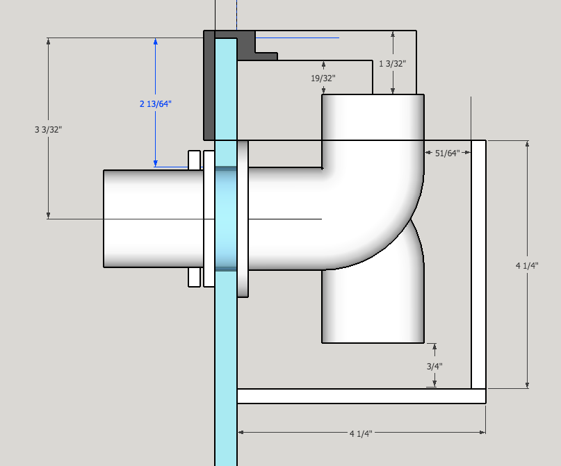
__________________
~~~~~~~~~~~~~~~~~~~~~ 120 gallon, coast to coast overflow w/beananimal overflow. Waveline DC 10000 II return pump, 40 gal sump, Octopus XS200 skimmer, T5 lighting Last edited by Misled; 03/25/2018 at 07:28 PM. |
|
|
|
|
05/29/2017, 02:49 PM
|
#9390 |
|
Registered Member
Join Date: May 2017
Posts: 16
|
Internal and External Overflows
I am in the process of having a 180 gallon 6 foot aquarium built and wanted to incorporate a beananimal system. I have been reading through the threads and have a couple of questions. Is the back glass the best place to build the internal weir and external overflow or can you use the side.
What are best dimensions to use for the internal weir and external overflow box. My plan is to have the internal weir built coast to coast along side pane or almost coast to coast if using the the back pane. The water would enter the external overflow box which I am also having built via 3 holes in the back or side glass. I plan to 1.5 inch bulkheads and PVC piping which flows down to my sump. As I having everything built from scratch including the sump I wanted to incorporate best practices so any guidance would be appreciated. |
|
|
|
|
05/29/2017, 04:22 PM
|
#9391 |
|
Registered Member
Join Date: Sep 2004
Location: Pennsylvania
Posts: 1,228
|
As far as drilling bulkhead holes in acrylic the answer theoretically is as close as you want provided you have room to work. I prefer schedule 80 because of beefiness of bulkhead and the added cost is negligible in my opinion. I surely wouldn't use schedule 40 if I was drilling the bottom of my tank for a closed loop as well.
The other post the overflow position in my opinion depends how the tank will be setup. |
|
|
|
|
05/29/2017, 05:19 PM
|
#9392 | |
|
Registered Member
Join Date: May 2017
Posts: 16
|
Quote:
|
|
|
|
|
|
05/29/2017, 10:13 PM
|
#9393 | |
|
Registered Member
Join Date: Oct 2011
Location: Minneapolis, MN
Posts: 3,907
|
Quote:
Note that the vast majority of tanks don't even use schedule 40 - they use ABS and never have any issues. The most common issue I've seen with ABS is when people over tighten threaded fittings and crack them. Aside from cost, the real drawback from the schedule 80 bulkheads is that they require larger holes which potentially weakens the tank more, particularly with glass tanks.
__________________
~~~~~~~~~~~~~~~~~~~~~ 120 gallon, coast to coast overflow w/beananimal overflow. Waveline DC 10000 II return pump, 40 gal sump, Octopus XS200 skimmer, T5 lighting |
|
|
|
|
|
05/29/2017, 10:18 PM
|
#9394 | |
|
Registered Member
Join Date: Oct 2011
Location: Minneapolis, MN
Posts: 3,907
|
Quote:
You can certainly have the internal overflow along the back with the holes placed far to one side. As I stated in my previous reply, the dimensions of the overflow box depend on the plumbing (and the materials from which it is made. 1.5" bulkheads are pretty big. How much flow are you looking for? Does the picture I posted above help you at all?
__________________
~~~~~~~~~~~~~~~~~~~~~ 120 gallon, coast to coast overflow w/beananimal overflow. Waveline DC 10000 II return pump, 40 gal sump, Octopus XS200 skimmer, T5 lighting |
|
|
|
|
|
05/29/2017, 11:26 PM
|
#9395 |
|
Registered Member
Join Date: May 2017
Posts: 16
|
Thanks everyone for your advice. My drain lines are planned to be 1.5” in the overflow box…my return lines are planned to be 1” in the upper right and left corner of the tank. The position of the return holes is why I can’t run the overflow “coast to coast”. However, given that the tank will be 7’ long, I suppose I could run it 4 or 5 feet if that would help? Does it help having more water in the overflow box…or less? Or does it not matter as long as the standpipe elbows are at the right height? Or does it help to have the downward facing standpipe elbows relatively close to the floor of the overflow box (like the ¾” distance in the drawing above).…to avoid junk settling on the floor of the box?
Regarding flow, the manufacturer of my tank tells me that each 1.5” bulkhead will drain about 1500 gph given my 6’ drop from top of tank to bottom of sump. Is that not accurate? Given that I’ll have about 250 gallons of water in my DT and another 75 or so gallons in the sump…and trying to achieve about 10X turnover per hour, that’s how I arrived at needing about 3000 gph. I also plan on Tee’ing off one of the drain lines to feed the refugium section of my sump. This is where I got the idea I might need to full siphon drainpipes running at 1500 each…….along with the one open channel standpipe and the one emergency standpipe. I also figured that if I end up needing only one of the full siphon drainpipes, or if having 2 causes an issue, I can just cap one off. Seems easier to cap one off later rather than drill one later! Am I way off in any of my thinking on this? The drawing of hole dimensions was VERY helpful! So thanks for that. Can I ask if the pipes in the drawing were 1”, 1.25” or 1.5”? If the drawing reflects pipes that are smaller than 1.5”, then I guess I need to adjust a bit for that? Does anyone already have that computed? Any harm in putting strainers on the ends of the standpipe elbows? Regarding the Open Channel standpipe, does it help to install an Airline valve on that line….or is fine-tuning of the air flow not necessary with this design? Thanks again for all the great ideas everyone…and your patience with all my questions! |
|
|
|
|
05/30/2017, 03:50 AM
|
#9396 | |
|
Registered Member
Join Date: May 2017
Posts: 16
|
Quote:
|
|
|
|
|
|
05/30/2017, 11:33 AM
|
#9397 | ||
|
Registered Member
Join Date: Oct 2011
Location: Minneapolis, MN
Posts: 3,907
|
Quote:
Regarding the overflow box, I place my elbows ¾" off the bottom to limit snails etc, but you also need to factor in the amount of flow you're running. The water level is determined by the open channel pipe. At steady state, the water level is generally about half way up the bulkhead for the open channel pipe. Remember, since it's normally entraining air, you could effectively remove the elbow from this pipe and not affect anything. What the elbow does is allow it to convert to a full siphon if the airline is occluded. Another thing to consider is that the flow into the siphon channel can create vortices from the water surface in the overflow box, causing it to entrain air and creating noise. This can be reduced by having a larger diameter elbow and having a deeper box. I'll have to check, but as I recall I used 1" bulkheads and 1.25" elbows for my overflow. I put a basket strainer around by elbow to keep snails out. You just have to keep in mind that it can restrict flow a bit. The open channel doesn't need a valve. Valves are used in a Durso to fine tune it and maximize the flow. With this design, the open channel is simply carrying the extra that the siphon doesn't. Quote:
__________________
~~~~~~~~~~~~~~~~~~~~~ 120 gallon, coast to coast overflow w/beananimal overflow. Waveline DC 10000 II return pump, 40 gal sump, Octopus XS200 skimmer, T5 lighting |
||
|
|
|
|
05/30/2017, 02:00 PM
|
#9398 |
|
Registered Member
Join Date: May 2017
Posts: 16
|
Thanks sleepydoc...Do you have pics of your setup?
|
|
|
|
|
05/30/2017, 04:24 PM
|
#9399 |
|
Registered Member
Join Date: May 2017
Posts: 16
|
Thanks again. Sleepydoc, regarding your diagram and dimensions for you drawing above for your 120 FWIW...what size pipe is that?
|
|
|
|
|
05/30/2017, 05:24 PM
|
#9400 |
|
Registered Member
Join Date: May 2017
Posts: 16
|
Having given this some thought I would like 1000 to 1200 gph flow....based on what you have stated I am assuming three i inch inch bulk heads should work?
|
|
|
|
 |
| Tags |
| beananimal, plumbing |
|
|


