
|
|
 03/13/2011, 12:30 AM
|
#1 |
|
Registered Member
Join Date: Oct 2009
Location: Lancashire, UK
Posts: 773
|
Matt's 5000ltr Display
Hi All
I have been lingering on your forum for some time now, I love it here. There have been so very many threads that I have read that have been inspiring that I simply couldnt name them all. However one thing I have noticed about RC is the depth of information that you folks go into and the care and attention you take in your build threads, seemingly as much care is taken with the thread as is with the build itself. The time you take to answer questions and keep members involved in your builds is inspiring in itself. Due to this and the afore mentioned threads i thought I would try my best to join in and contribute to what is a great forum with some great members. OK, so where to begin? I have been in the hobby for some years now, starting with a 200ltr tank and quickly moving onto a 500ltr tank with about 150ltr sump. I should just point out now that I am in the UK so I will stick to litres as opposed to gallons as they would get lost in translation. On to the new tank. I have been planning this for approximately 2 years. If truth be told I dont think it needed that amount of planning but life constantly got in the way of me actually making a start. So I should correct that statement: I have been planning it for 5 months and daydreaming about the opportunity to start it for 19 months! I will try to quickly get you up to speed with where I am at the moment but I think it is important to start at the begining to show how the current design evolved over time and why i made the decisions I did. The 10ft tank will be residing in my dining room, it will span one wall. Below is my first design, swiss cheese. With 3 seperate CL systems, multiple drains and feeds it was going to have too many holes for my liking so I soon abandoned this idea. 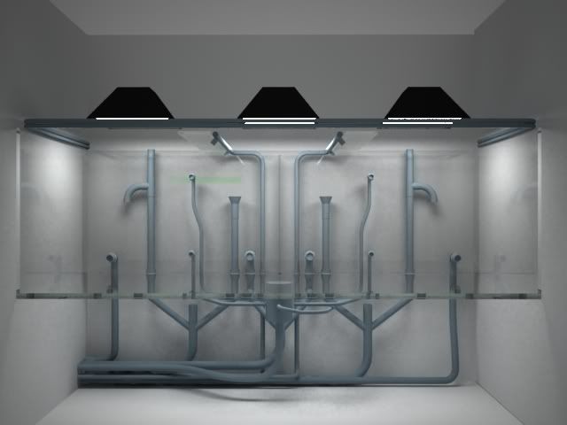 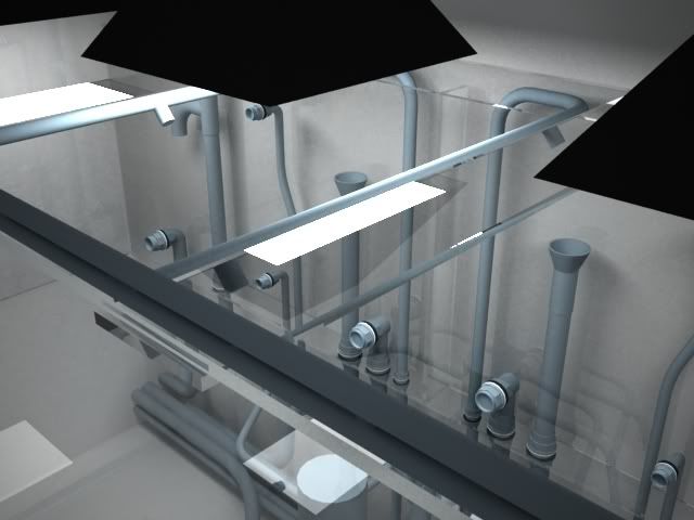 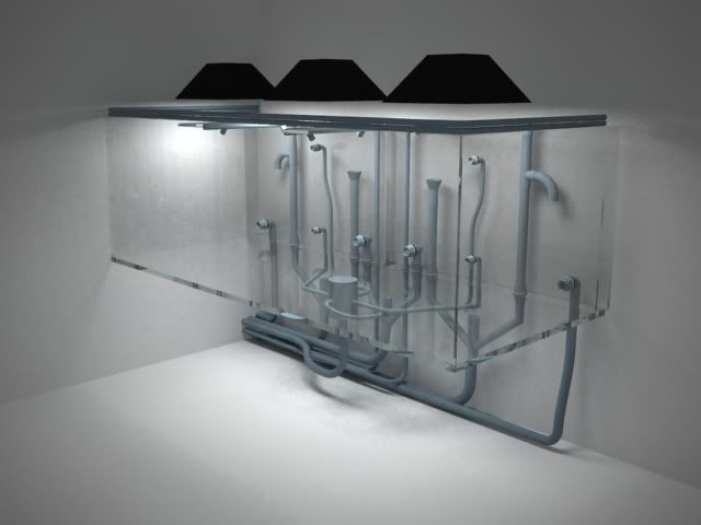
|

|

|
|
03/13/2011, 12:39 AM
|
#2 |
|
Registered Member
Join Date: Oct 2009
Location: Lancashire, UK
Posts: 773
|
The idea was to build the tank and utilise the space underneath for my daughters ever increasing amount of toys. I didnt want the restrictions that I currently face with the sump under the tank I wanted what you boys and girls call a "fish room"
Space here in the UK is somewhat limited to what you experience in what would seem most parts of North America and Canada so i had to think of a design that I could accomodate the filtration for in my garage that was 6ft away from the dining room. Below is a floor plan of the proposed design 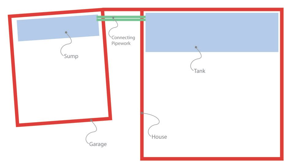 The idea was that the drains would leave the tank, go through the cavity brick wall to the outside. They would then drop to ground level, travel the 6ft to the garage, go through the garage wall and into the sump...easy eh? |
|
|
|
|
03/13/2011, 12:47 AM
|
#3 |
|
Registered Member
Join Date: Oct 2009
Location: Lancashire, UK
Posts: 773
|
This to me seemed to over complicate what is essentially a simple principle. Winters can get pretty cold here...summers can be pretty nippy too!! So I had concerns about sufficently insulating the pipes. Although the water would be moving it would still have the opportunity to chill slightly and so I would be using more watts to keep it at a steady 25/26 degrees.
I decided to have the garage extended to meet the house and allow for the pipes to pass through the cavity wall straight into the garage/fish room. 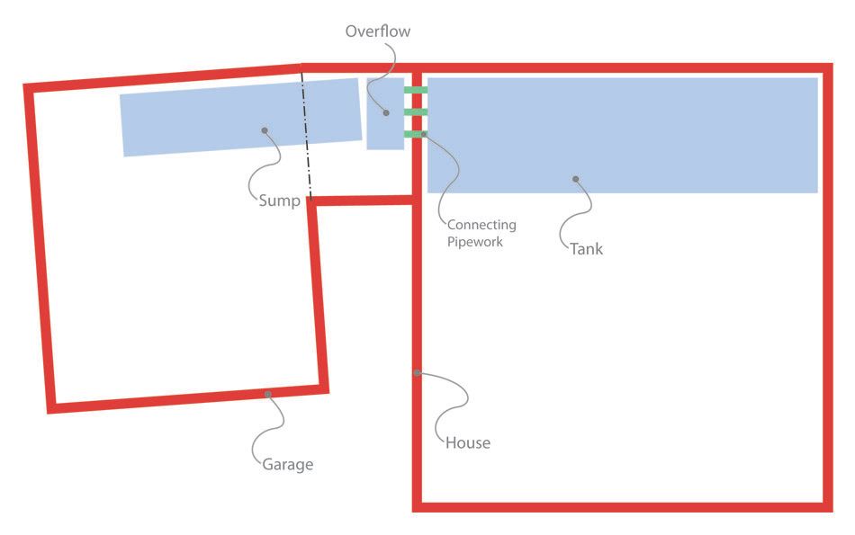
|
|
|
|
|
03/13/2011, 01:04 AM
|
#4 |
|
Registered Member
Join Date: Jan 2004
Location: San Francisco
Posts: 9,103
|
Instead of physically connecting the two structures (which can run into it's own issue) you could simply build a box around the outside pipes and insulate the hell out of it, something like expanding foam would work nice. Also is your garage insulated? Most aren't around here. It would stink if you had to burn through electricity because your garage is near freezing sucking heat from your sump.
That said how much to scale is your house/garage... looks like your tank will take up 20% of the living space!
__________________
Mike |
|
|
|
|
03/13/2011, 11:12 AM
|
#5 | ||
|
Registered Member
Join Date: Oct 2009
Location: Lancashire, UK
Posts: 773
|
Quote:
Quote:
Also I will be having a partition added to the garage so that the fish room area is easier to control temperature wise. The drawings above are not to scale, just for positioning of the tank vs sump to give you an idea. What is actually called "house" in the drawing is just one room. The tank is big but not that big. |
||
|
|
|
|
03/13/2011, 11:17 AM
|
#6 |
|
Registered Member
Join Date: Apr 2010
Location: Dubai
Posts: 14
|
I have been through this process of thought although I have to do the other way around... Cool the water as in sumer it hits 45 deg outside so I inverted all to be in the same place under the display tank...
I am interested to see your final thoughts and plan of action.. Wish u luck |
|
|
|
|
03/13/2011, 11:23 AM
|
#7 |
|
Registered Member
Join Date: Jan 2010
Location: Canadia
Posts: 4,276
|
May I ask what software you used to do your 3D drawings? Looks way cool.
Dave.M
__________________
My Gawd! It's full of corals! Current Tank Info: None. Nil. Zip. Nada. |
|
|
|
|
03/13/2011, 11:23 AM
|
#8 |
|
Registered Member
Join Date: Oct 2009
Location: Lancashire, UK
Posts: 773
|
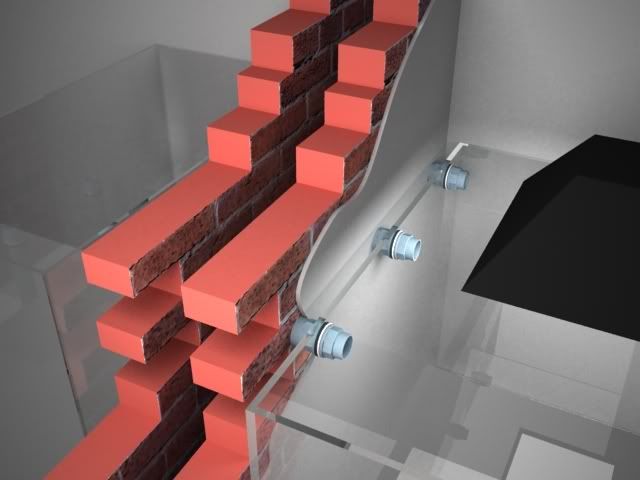
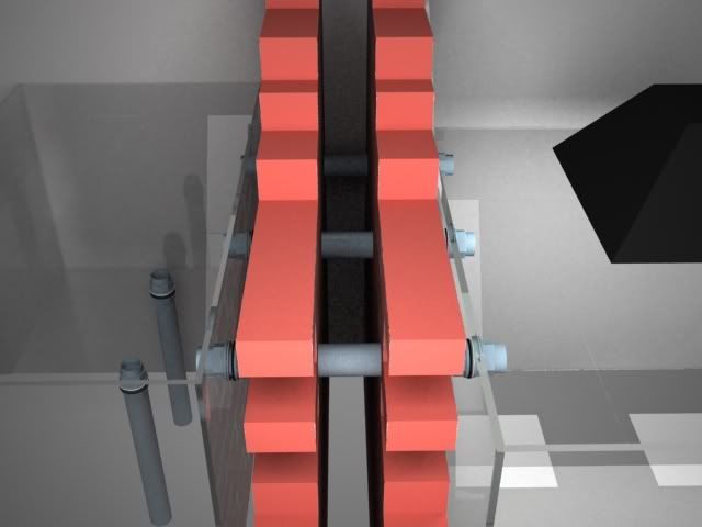
Having had the garage extended I could then take the pipework through the cavity wall on the left of the tank to an overflow box that was sat in the garage.
|
|
|
|
|
03/13/2011, 11:25 AM
|
#9 | |
|
Registered Member
Join Date: Oct 2009
Location: Lancashire, UK
Posts: 773
|
Quote:
Thanks Matt |
|
|
|
|
|
03/13/2011, 12:08 PM
|
#10 |
|
Registered Member
Join Date: Oct 2009
Location: Lancashire, UK
Posts: 773
|
Next I started to plan the lighting.
I bought 4 x lumenarcIII reflectors and 6 coral vue ballasts. The ballasts were made up of 4 x 250w and 2 x 400w. I plan to set the tank up with 2x400w centrally with a 250w either side. In the future if i chose to I can drop the 400w centrally and replace with 250's ( this was the reasoning behind buying the extra two ballasts) 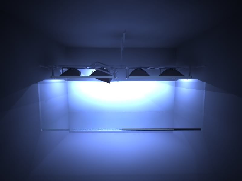 I wanted to be able to rotate the lights rather than have the conventional "straight down" lighting. I wanted to be able to rotate the lights away from the front glass and light the tank more like a stage. So I set about trying to figure out a gimbal sort of arrangement for the lumenarc reflectors. 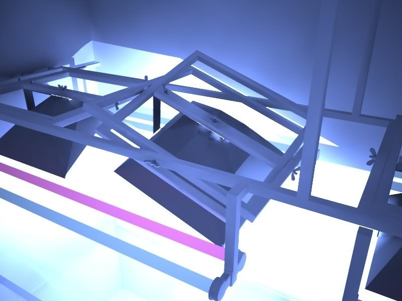 Out of all the planning the lighting gave me the most headaches and therefore the lighting rig constantly changed...more about that later. 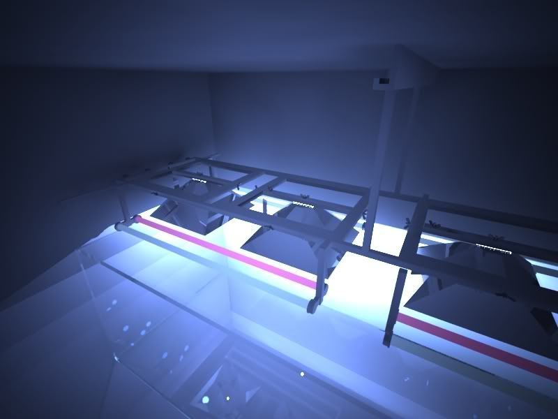
|
|
|
|
|
03/13/2011, 12:29 PM
|
#11 |
|
Registered Member
Join Date: Oct 2009
Location: Lancashire, UK
Posts: 773
|
The next issue to address was flow and how to get lots of it!
Personally I am not a fan of powerheads especially in a 5000ltr display so I chose to opt of closed loops, several of them. The return from the sump will be 16000lph and will be delivered back to the tank via a calfo loop. 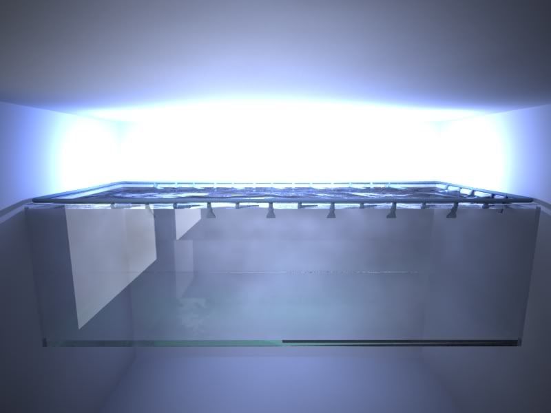 50% of the nozzels will be directed across the waters surface and 50% down towards the reef. 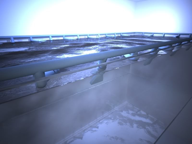 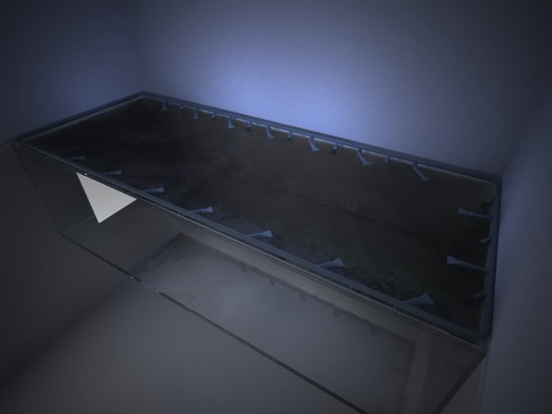
|
|
|
|
|
03/13/2011, 01:08 PM
|
#12 |
|
Registered Member
Join Date: Jan 2009
Location: Lebanon Me
Posts: 114
|
What holds it up? Very interesting design. Tagging along
|
|
|
|
|
03/13/2011, 01:12 PM
|
#13 | |
|
Registered Member
Join Date: Oct 2009
Location: Lancashire, UK
Posts: 773
|
Quote:
 Infact the stand has been built. These drawings are just my workings out. Infact the stand has been built. These drawings are just my workings out.
|
|
|
|
|
|
03/13/2011, 01:20 PM
|
#14 |
|
Registered Member
Join Date: Oct 2009
Location: Lancashire, UK
Posts: 773
|
I had the good fortune to visit David Saxby and spend some time with him discussing flow, his tank is stunning and I would have been foolish to not take on board his thoughts on flow and closed loops.
So I simply stole his ideas and designs  These are early drawings and things have moved on a little from this design. There will be 4 seperate closed loop systems totalling 64000lph. Each fed from a seperate 16000lph laguna pump. 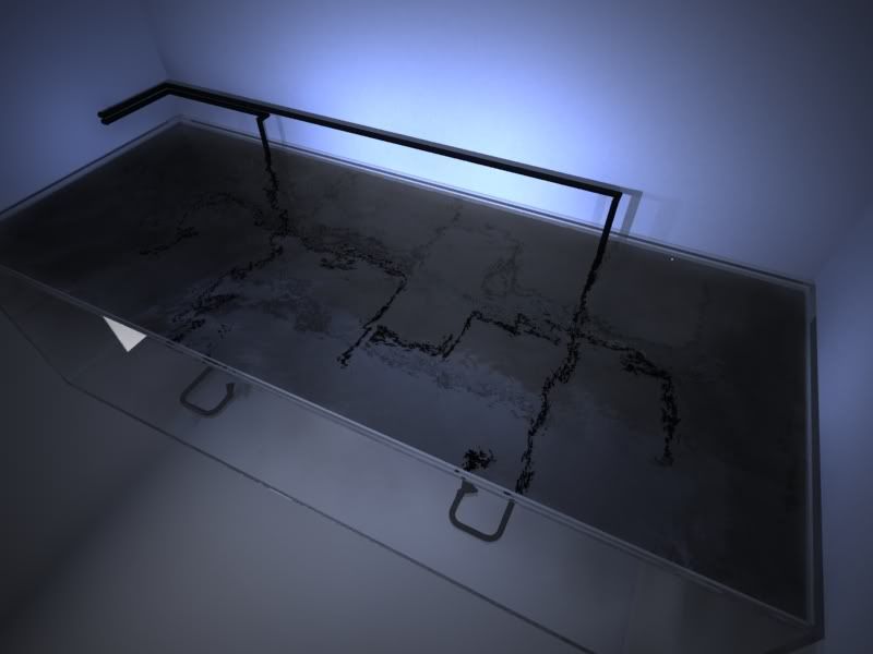 The idea behind it was that I can turn a couple of the pumps off for quieter/gentle night time flow but still not have any dead spots. One of the pumps will feed an OM 4 way with revolutions. 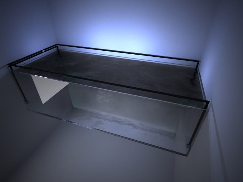 There will be a single revolution in each corner. 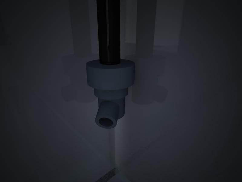 You will notice that no holes are drilled in the tank to feed the closed loops back. This was another suggestion from David Saxby, by limiting the amount of holes in a tank limits the amount of things that can go wrong....maybe not today, not tomorrow but someday. |
|
|
|
|
03/13/2011, 01:32 PM
|
#15 |
|
Registered Member
Join Date: Jan 2010
Location: Canadia
Posts: 4,276
|
Stunning images! This is turning into a graphic novel.
 Dave.M
__________________
My Gawd! It's full of corals! Current Tank Info: None. Nil. Zip. Nada. |
|
|
|
|
03/13/2011, 01:42 PM
|
#16 | |
|
Registered Member
Join Date: Oct 2009
Location: Lancashire, UK
Posts: 773
|
Quote:
At least the workload meant that I have designed the hell out of the tank, I know exactly how it will work and now that it has been started I have used the drawings as reference so that (hopefully) I wont make any errors. |
|
|
|
|
|
03/13/2011, 01:55 PM
|
#17 |
|
Registered Member
Join Date: Oct 2009
Location: Lancashire, UK
Posts: 773
|
fibreglass??
I started to get some quotes from "build on site" aquarium companies.
All I can say is "wow". I dont know how it is for you over there but here in the UK glass prices have gone up 5 fold over the last couple of years. The average price I was quoted for 120" x 48" x 48" was about £12,000. Which in your money is about $19,308.95 (using xe.com) I could have dropped a foot off of the height making it 36" high so the glass could be thinner. This dropped the price to an average of £4000. But I had planned and dreamed of this tank for a long time. I didnt want to sacrifice my plans due to cost to then look at my 36" deep tank wishing I had stuck to my guns. I was prepared to pay the $19k and change to have the tank I wanted. Speaking to a friend and fellow reefer one day and discussing my plans he asked me if i had explored a fibreglass tank? I hadn't...I hadn't even heard of a fibreglass tank other than those at public displays. So I spent some time reading every thread I could find relating to fibreglass tanks. |
|
|
|
|
03/13/2011, 05:45 PM
|
#18 |
|
Registered Member
Join Date: Oct 2009
Location: Lancashire, UK
Posts: 773
|
to cut a long story short it turned out that a fibreglass tank would suit my requirements pretty well.
With only a single viewing pane of glass and with the tank surrounded on 3 sides by brick walls there was no need to pay for glass that wouldnt be needed. 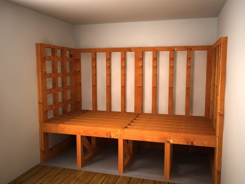 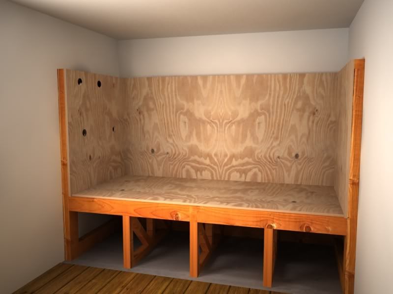 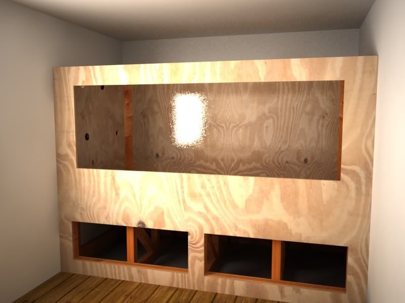
|
|
|
|
|
03/13/2011, 05:51 PM
|
#19 |
|
Registered Member
Join Date: Oct 2009
Location: Lancashire, UK
Posts: 773
|
The end goal,
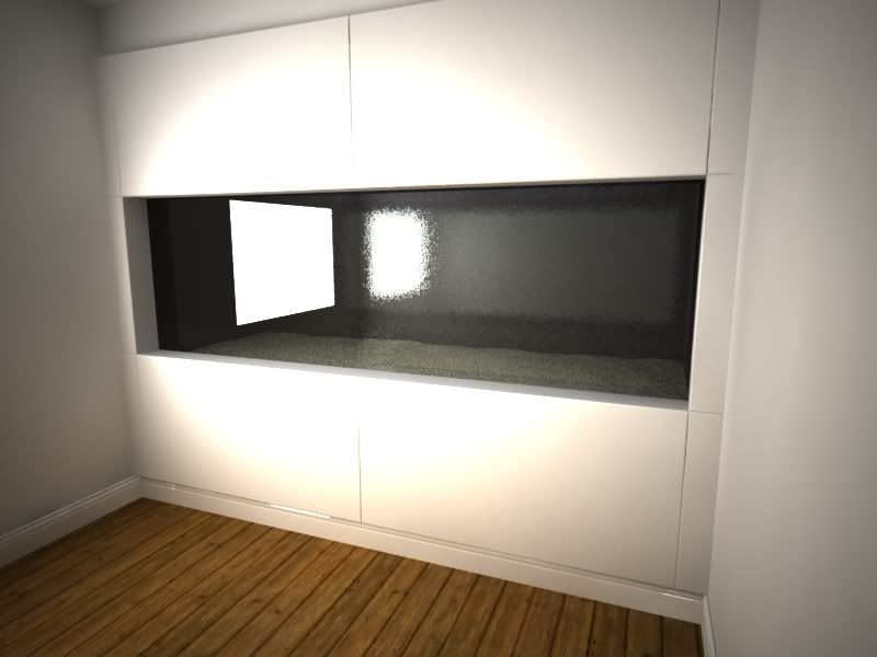 If anyone has ever seen Ralfp's tank they will recognise this cabinetry design, another idea I have stolen
|
|
|
|
|
03/13/2011, 06:41 PM
|
#20 |
|
Registered Member
Join Date: Apr 2007
Location: Easton, PA
Posts: 619
|
wow.. i feel dumb didn't realize this was a sketch and was wondering how that tank was floating... lol
cant wait looks amazing.
__________________
Ricky |
|
|
|
|
03/13/2011, 07:22 PM
|
#21 |
|
Registered Member
Join Date: Oct 2009
Location: Lancashire, UK
Posts: 773
|
No probs Ricky. I wanted the first few posts to get you all up to speed thats all. There will be some proper pictures to follow.
I must warn you however that my work commitments will mean it is a slow build. |
|
|
|
|
03/13/2011, 07:28 PM
|
#22 |
|
Registered Member
Join Date: Oct 2009
Location: Lancashire, UK
Posts: 773
|
A plus point of the fibre glass route is that I can have more tank than the viewing panel shows.
I like the idea of fish swimming into view from the left or right, also the sand bed will be well away from the glass. I have allowed for 12" of tank below the glass so could have a 6" DSB in the tank and still have 6" of clearance before the glass....no more algae build up that is difficult to scrape off! 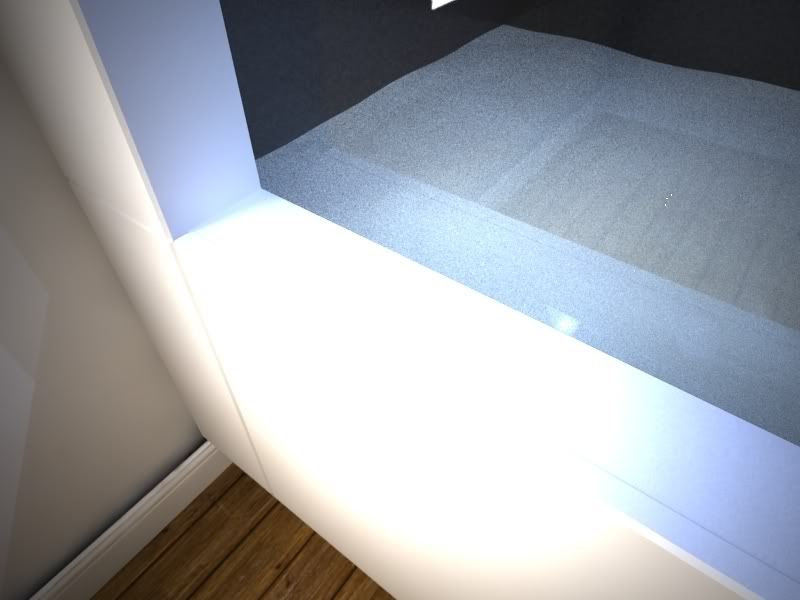
|
|
|
|
|
03/13/2011, 08:09 PM
|
#23 |
|
Registered Member
Join Date: Oct 2009
Location: Lancashire, UK
Posts: 773
|
Filtration
My proposed filtration might take a little explaining, I hope the drawings help but as things have altered a little from the time of drawing them they may get a little confusing.
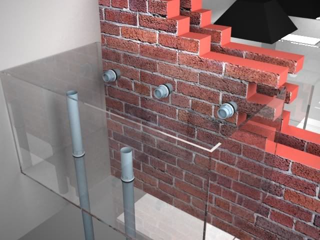
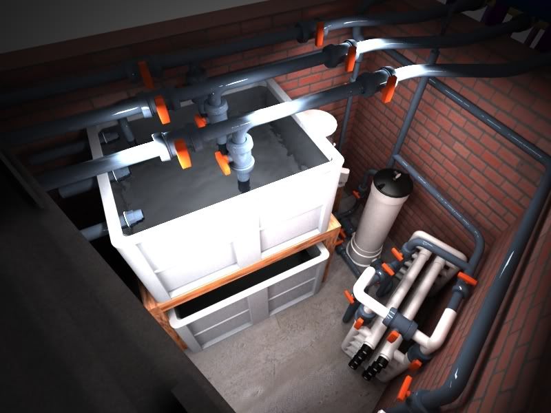 This view shows inside the extension I had built to join the garage with the house. This is the first section of the filtration. There will be 3 x 63 mm drains from the tank, one of which will gravity feed a deltec 3070 skimmer. The other two pipes will feed into a 600ltr plastic vat ( similar sort of affair to what I have seen you boys and girls do with rubbermaids) The first 600ltr vat will be a sort of sediment tank. There will be 300 micron filter socks that the pipes will drain into. As you can see from the drawing this vat can be isolated. i will be able to drain it via a ball valve under its base, refill will fresh RO, heat and salt and then add it back onto the system. This will be how I foresee me doing water changes. |
|
|
|
|
03/13/2011, 08:21 PM
|
#24 |
|
Registered Member
Join Date: Oct 2009
Location: Lancashire, UK
Posts: 773
|
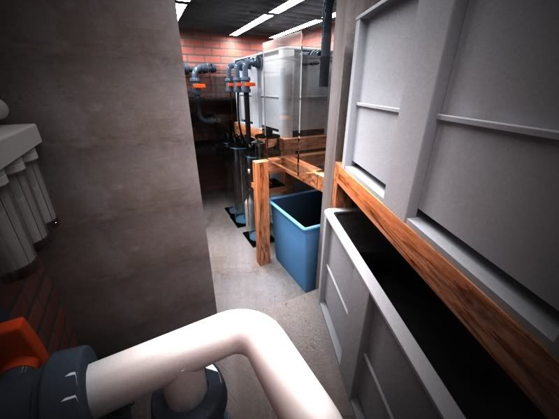 Looking back towards the rest of the filtration. After the sediment tank some of the flow will break off to a 500ltr glass tank which will be home for an algae turf scrubber. The rest of the flow will continue to the next 600ltr vat that will be a cryptic zone. The cryptic zone will have bulkheads that will feed a deltec nitrate reactor, calcium reactor and phosphate reactor. All the reactors will feed into the 600ltr vat below the cryptic zone. Following on from the cryptic zone will be a series of small glass tanks that will be breeder and frag tanks. 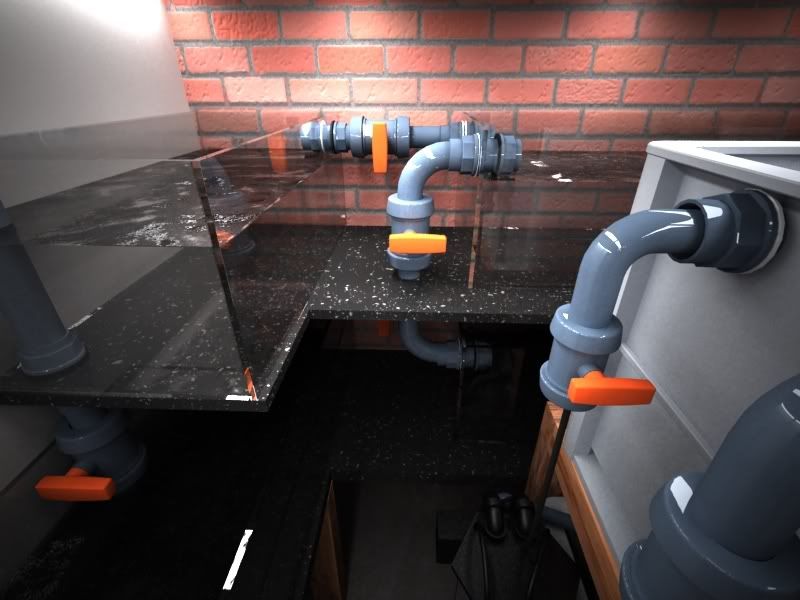
|
|
|
|
|
03/13/2011, 08:29 PM
|
#25 |
|
Registered Member
Join Date: Oct 2009
Location: Lancashire, UK
Posts: 773
|
The cryptic tank and breeder and frag tanks aswell as the reactors will feed into the 600ltr DSB vat. The DSB flow will pass the 400ltr RO top up that will feed a kalk stirrer (blue vat in the drawings) and into the 600ltr return section.
The return pump will be a 16000lph laguna pump and before returning to the display will pass through a 400w UV and a TMC commercial filter canister 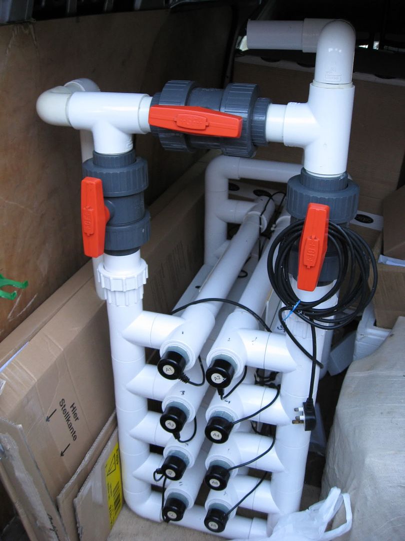 Pic of the UV. The filtration will terminate as a calfo loop on the display tank |
|
|
|
 |
|
|
 Similar Threads
|
||||
| Thread | Thread Starter | Forum | Replies | Last Post |
| display refugium- lighting, macro and coral beauty? | Moonstream | Reef Discussion | 5 | 03/12/2011 05:35 PM |
| Macro algae in Display Tank? | calziereef | Marine Plants & Macroalgae | 2 | 07/29/2010 09:53 PM |
| Matt's Nano | meschaefer | Large Reef Tanks | 12 | 06/05/2007 11:22 AM |
| Matt's 110 progress report | McCrary | Arizona-Sierra Vista/Tucson Reef Keepers | 10 | 09/29/2006 09:28 PM |


