Reef Central Online Community

Go Back   Reef Central Online Community > General Interest Forums > Do It Yourself
Blogs FAQ Calendar

Notices

User Tag List

Reply
Thread Tools
Unread 02/16/2012, 12:17 PM   #1251
crazyreef09
Registered Member
 
Join Date: Oct 2010
Posts: 18
Quote:
Originally Posted by katchupoy View Post
int blueramptime = 60 ; // time for blue LEDs to dim on and off in minutes
int whiteramptime = 120 ; // time for white LEDs to dim on and off in minutes
int photoperiod = 240 ; // amount of time array is on at full power in minutes
int ontime = 12 ; // time of day (hour, 24h clock) to begin photoperiod

So from here the blue light starts at 12 and fades in for the first 60 minutes and then what? Does the White light starts fading in at this point or does the 120 minutes are counted from 12 pm? The white will start ramping in after the 60min mark. Then it will continue to ramp up for the next 120 min. I am confused, can anyone clarify this?

then after the white have fully ramp up, it will stay there for the next 4 hours. Then it will start to ramp down, white first for 2 hours then blue for 1 hour.

Hope this helps.
Thanks a lot for the help katchupoy, this clarifies my problem.

As for problem #2 for the temperature probe I am still having problems, yesterday I had it all working and today the temperature was basically stuck at 76 and when I uploaded a new code it showed 185F. Can the probe be bad? I did wire the 4k7 resistor. Any help will be appreciated.


crazyreef09 is offline   Reply With Quote
Unread 02/16/2012, 01:46 PM   #1252
crazyreef09
Registered Member
 
Join Date: Oct 2010
Posts: 18
I think I figured out what my problem with the temperature is.
The temperature readings are getting stuck once the arduino is doing the fading of the blues and whites, once that is done and the leds are at 0 or 255 the temp readings become actual temp readings. So whatever the last temp reading was when the fading starts is the reading that will be shown until the fading is over. The alarm will not even respond during this stage even if the temp shown is lower than the set temp for the alarm.

Did anybody else notice this? I am using Version_1_00_16x2. Do the other versions have the same problem or was it fixed? Thanks.


crazyreef09 is offline   Reply With Quote
Unread 02/16/2012, 09:30 PM   #1253
katchupoy
Moved On
 
katchupoy's Avatar
 
Join Date: Feb 2003
Location: Kent, WA
Posts: 1,548
Quote:
Originally Posted by crazyreef09 View Post
I think I figured out what my problem with the temperature is.
The temperature readings are getting stuck once the arduino is doing the fading of the blues and whites, once that is done and the leds are at 0 or 255 the temp readings become actual temp readings. So whatever the last temp reading was when the fading starts is the reading that will be shown until the fading is over. The alarm will not even respond during this stage even if the temp shown is lower than the set temp for the alarm.

Did anybody else notice this? I am using Version_1_00_16x2. Do the other versions have the same problem or was it fixed? Thanks.
I will bump this for you so that others can see your issues. I am sorry that I cannot help you with this since my original build does not have this feature.
Hope others can help you.


katchupoy is offline   Reply With Quote
Unread 02/21/2012, 11:34 AM   #1254
buck27
Registered Member
 
buck27's Avatar
 
Join Date: Sep 2010
Posts: 102
I just ordered a bunch of stuff so I will be trying to build a controller as well. I hope you don't mind alot of questions and providing some help as I have zero experience with programming and zero experience with electronics but if I ask the right questions and get the right guidance I should be able to this (I hope) thanks guys.


__________________
Buck
buck27 is offline   Reply With Quote
Unread 02/21/2012, 12:07 PM   #1255
katchupoy
Moved On
 
katchupoy's Avatar
 
Join Date: Feb 2003
Location: Kent, WA
Posts: 1,548
Im sure what you are looking for is here somewhere. Just keep on reading, i guess.


katchupoy is offline   Reply With Quote
Unread 02/27/2012, 03:17 PM   #1256
Dan_Cochran
Registered Member
 
Join Date: Feb 2012
Location: Michigan
Posts: 10
katchupoy, Very long, but Very informative thread. Nice Job to all ! Thank you!

I have never worked with a arduino before, and so far there is so much info here my controller is almost complete.

main parts i have are SainSmart Arduino Uno w/ the 16x2 button sheld, SainSmart 4 relay 5v module, rtc. 2 temp from ebay, and cree led, three 48p drivers 12 white 24 blue and the 10v wall plug from rapid

I still am in the process of putting everything in the radio shack project box's, but have some Questions.

I have not tested the drivers yet with this but the relays are giving me issues. relay 1 and 2 seem to click on and off correct, but 3 and 4 have issues.
but temps and clock works

digital
pin 13 relay 1 Powerhead
pin 12 open
pin 11 led white
pin 3 led blue
pin 2 relay 2 other powerhead
pin 1 temps
pin 0 moon or sump light "not installed yet on tank, another non dim driver cree led"


analog
a1 "set to ph, have no clue when i would build this"
a2 "want for relay 3" for fuge light
a3 Relay 4 " to fun my fans"
a4 and a5 for RTC


i will post the code in a min. see is anyone can fix a few issues. Thanks


Dan_Cochran is offline   Reply With Quote
Unread 02/27/2012, 03:19 PM   #1257
Dan_Cochran
Registered Member
 
Join Date: Feb 2012
Location: Michigan
Posts: 10
code i am having issues with

PHP Code:
#include <OneWire.h>
#include <DallasTemperature.h>
#include <Wire.h>                 // Comunication I2C 
#include <LiquidCrystal.h>
#include <DS1307.h>
#include "RTClib.h"
#define DS1307_I2C_ADDRESS 0x68 //set rtc
#define ONE_WIRE_BUS 1 //Define the pin of the DS18B20

#define DISPLAYTIMEOUT 2000   // every second next screen
unsigned long lastDisplay 0;

int screenID 0;

/************************************************* H A R D W A R E **********************************************************************/

int fuge A2;             // fuge light power relay connected to analog pin 1
int heater 31;           // Heater
int fan A3;              // Fan power relay connected to analog pin 0 is pin2
int moon 0;              // moon light connected to digital pin 3
int ph_probe 28;          // pH probe on Analog 1
int orp_probe 29;         // ORP probe on Analog 2
int alarm 41;             // Alarm

/*|||||||||||||||||||||||||||||||||||||||||||||||||||||||||||||||||  R E L A Y   P A R T  |||||||||||||||||||||||||||||||||||||||||||||||||||||||||||*/
/*|||||||||||||||||||||||||||||||||||||||||||||||||||||||||||||||||  S I M P L E   O N   A N D   O F F   F E A T U R E |||||||||||||||||||||||||||||||||||||||||||||||||||||||||||*/


const int ledPin1 =  13;          // pin number for relay 1
const int ledPin2 =  2;          // pin number for relay 2


int ledState1 LOW;             
int ledState2 HIGH
long previousMillis1 0;        
long previousMillis2 0;
long interval1 3000;          // interval at which to blink (milliseconds) for RELAY1
long interval2 3000;         // interval at which to blink (milliseconds) for RELAY2


/*|||||||||||||||||||||||||||||||||||||||||||||||||||||||||||||||||  L E D   D I M M I N G   P A R T  |||||||||||||||||||||||||||||||||||||||||||||||||||||||||||*/
/*|||||||||||||||||||||||||||||||||||||||||||||||||||||||||||||||||  F A D E S   I N   A N D   O U T  |||||||||||||||||||||||||||||||||||||||||||||||||||||||||||*/


int blueramptime 60 ;    // time for blue LEDs to dim on and off in minutes
int whiteramptime 120 ;  // time for white LEDs to dim on and off in minutes
int bluemin ;          // minimmum dimming value of blue LEDs, range of 0-255
int bluemax 255 ;        // maximum dimming value of blue LEDs, range of 0-255
int whitemin ;         // minimum dimming value of white LEDs, range of 0-255
int whitemax 255 ;       // maximum dimming value of white LEDs, range of 0-255
int photoperiod 360 ;    // amount of time array is on at full power in minutes
int ontime ;          // time of day (hour, 24h clock) to begin photoperiod fade in
int blue 3;              // blue LEDs connected to digital pin 3 (pwm)
int white 11;            // white LEDs connected to digital pin 11 (pwm)


//int bluepercent[11] = { 0, 1, 2, 5, 8 ,12, 18, 27, 44, 80, 255 };   // this line is needed if you are using meanwell ELN60-48D
//int whitepercent[11] = { 0, 1, 2, 5, 8 ,12, 18, 27, 44, 80, 255 };   // these are the values in 10% increments

int bluepercent[11] = { 0265278103128154180205230255 };   // this line is needed if you are using meanwell ELN60-48P
int whitepercent[11] = { 0265278103128154180205230255 };   // these are the values in 10% increments

/*************************************************************************** A T O *******************************************************/
int ato_time_day 0// Number of seconds the ATO runs each time during day time.
int ato_time_night 0// Number of seconds the ATO runs each time during night time.
int ato_time 0// Number of seconds for the ATO to run each time the switch is on.
int ato_count 0// Counts how many time ATO is active (ato_count X 50 ml = ml/day)
int ato_hour 0;


#define NUMREADINGS_ph 60
int readings_ph[NUMREADINGS_ph]; // The readings from the analog input
#define NUMREADINGS_orp 60
int readings_orp[NUMREADINGS_orp]; // The readings from the analog input

int index_ph 0// The index of the current pH reading
int index_orp 0// The index of the current ORP reading

int total_orp 0;
int total_ph 0;

int average_orp 0;
int average_ph 0;
int orp_val 350;        // Comment out after done testing
int orp_Loworp_Highph_valph_Lowph_HighWholeFract;


LiquidCrystal lcd(8,9,4,5,6,7);


// Setup a oneWire instance to communicate with any OneWire devices (not just Maxim/Dallas temperature ICs)
OneWire oneWire(ONE_WIRE_BUS);

// Pass our oneWire reference to Dallas Temperature. 
DallasTemperature sensors(&oneWire);
/*|||||||||||||||||||||||||||||||||||||||||||||||||||||||||||||||||  R T C   C L O C K   D S 1 3 0 7  |||||||||||||||||||||||||||||||||||||||||||||||||||||||||||*/


byte decToBcd(byte val)    // Convert normal decimal numbers to binary coded decimal
{
  return ( (
val/10*16) + (val%10) );
}


byte bcdToDec(byte val)    // Convert binary coded decimal to normal decimal numbers
{
  return ( (
val/16*10) + (val%16) );
}

// 1) Sets the date and time on the ds1307
// 2) Starts the clock
// 3) Sets hour mode to 24 hour clock
// Assumes you're passing in valid numbers
void setDateDs1307(byte second// 0-59
byte minute// 0-59
byte hour// 1-23
byte dayOfWeek// 1-7
byte dayOfMonth// 1-28/29/30/31
byte month// 1-12
byte year// 0-99
{
  
Wire.beginTransmission(DS1307_I2C_ADDRESS);
  
Wire.send(0);
  
Wire.send(decToBcd(second)); // 0 to bit 7 starts the clock
  
Wire.send(decToBcd(minute));
  
Wire.send(decToBcd(hour));   // If you want 12 hour am/pm you need to set
  // bit 6 (also need to change readDateDs1307)
  
Wire.send(decToBcd(dayOfWeek));
  
Wire.send(decToBcd(dayOfMonth));
  
Wire.send(decToBcd(month));
  
Wire.send(decToBcd(year));
  
Wire.endTransmission();
}

// Gets the date and time from the ds1307
void getDateDs1307(byte *second,
byte *minute,
byte *hour,
byte *dayOfWeek,
byte *dayOfMonth,
byte *month,
byte *year)
{
  
// Reset the register pointer
  
Wire.beginTransmission(DS1307_I2C_ADDRESS);
  
Wire.send(0);
  
Wire.endTransmission();

  
Wire.requestFrom(DS1307_I2C_ADDRESS7);

  
// A few of these need masks because certain bits are control bits
  
*second bcdToDec(Wire.receive() & 0x7f);
  *
minute bcdToDec(Wire.receive());
  *
hour bcdToDec(Wire.receive() & 0x3f); // Need to change this if 12 hour am/pm
  
*dayOfWeek bcdToDec(Wire.receive());
  *
dayOfMonth bcdToDec(Wire.receive());
  *
month bcdToDec(Wire.receive());
  *
year bcdToDec(Wire.receive());
}

/*|||||||||||||||||||||||||||||||||||||||||||||||||||||||||||||||||  D E F I N E  :  O N E S E C O N D |||||||||||||||||||||||||||||||||||||||||||||||||||||||||||*/


void onesecond() //function that runs once per second while program is running
{
  
byte secondminutehourdayOfWeekdayOfMonthmonthyear;
  
getDateDs1307(&second, &minute, &hour, &dayOfWeek, &dayOfMonth, &month, &year);
    if (
millis() - lastDisplay DISPLAYTIMEOUT )   
  {
    
lastDisplay millis();
    
doDisplay();
   }
  
lcd.setCursor(00);
  if(
hour>0)
  {
    if(
hour<=12)
    {
      
lcd.print(hourDEC);
    }
    else
    {
      
lcd.print(hour-12DEC);
    }
  }
  else
  {
    
lcd.print("12");
  }
  
lcd.print(":");
  if (
minute 10) {
    
lcd.print("0");
  }
  
lcd.print(minuteDEC);
  
//lcd.print(":");
  //if (second < 10) {
  //  lcd.print("0");
  //}
  //lcd.print(second, DEC);
  
if(hour<12)
  {
    
lcd.print("AM");
  }
  else
  {
    
lcd.print("PM");
  }
  
lcd.print(" ");

  
lcd.setCursor(8,0);
  
lcd.print(month,DEC);
  
lcd.print("/");
  
lcd.print(dayOfMonth,DEC);
  
lcd.print("/");
  
lcd.print(year,DEC);
  
lcd.print(" ");
  
delay(1000);
}


/*|||||||||||||||||||||||||||||||||||||||||||||||||||||||||||||||||  S C R O L L P A R T  |||||||||||||||||||||||||||||||||||||||||||||||||||||||||||*/
void doDisplay()
{
  
screenID constrain(screenID05);
  switch(
screenID)
  {
    case 
lcd.clear();
        
lcd.setCursor(01);
        
lcd.print("W Temp: ");
        
lcd.print(sensors.getTempFByIndex(0)); 
        
lcd.print((char)223);
        
lcd.print("F");

      break;
    case 
lcd.clear();
        
lcd.setCursor(01);
        
lcd.print("L Temp: ");
        
lcd.print(sensors.getTempFByIndex(1)); 
        
lcd.print((char)223);
        
lcd.print("F");
      break;
    case 
lcd.clear();
        
lcd.setCursor(0,1);
        
lcd.print("Heat:");
        
lcd.setCursor(5,1);
        if(
digitalRead(heater) == HIGH){lcd.print("On");}
          else{
lcd.print("Off");}
        
lcd.setCursor(91);
        
lcd.print("Fan:");
        
lcd.setCursor(13,1);
        if(
analogRead(fan) == 255){lcd.print("On");}
          else{
lcd.print("Off");}
      break;
    case 
lcd.clear();
        
lcd.setCursor(0,1);
        
lcd.print("Moon:");
        
lcd.setCursor(5,1);
        if(
digitalRead(moon) == HIGH){lcd.print("On");}
          else{
lcd.print("Off");}
        
lcd.setCursor(81);
        
lcd.print("Fuge:");
        
lcd.setCursor(13,1);
        if(
analogRead(fuge) == 255){lcd.print("On");}
          else{
lcd.print("Off");}
      break;
    case 
lcd.clear();
        
lcd.setCursor(0,1);
        
lcd.print("pH:");
        if (
Whole >= 10) {
        
Whole 9;
          }
        
lcd.print(WholeDEC);
        
lcd.print(".");
        if (
Fract 10){
        
lcd.print("0");
          }
        
lcd.print(FractDEC);
      break;
    case 
lcd.clear();
        
lcd.setCursor(1,1);
        
lcd.print("ORP:");
    
//lcd.print("Do Not Touch !");
        
lcd.setCursor(5,1);
        
lcd.print(orp_val);
        
lcd.setCursor(8,1);
        
lcd.print("mV");
     break;

    default: 
// should not happen => reset screenID
      
screenID 0;
      break;
  }
screenID++;    // sert next screen 
  
if (screenID 5screenID 0;  //  wrap around if all screens done
}


/*|||||||||||||||||||||||||||||||||||||||||||||||||||||||||||||||||  D E F I N E  :  F U G E  L I G H T  O N |||||||||||||||||||||||||||||||||||||||||||||||||||||||||||*/
void FugeOn()
{
  
//digitalWrite(fuge, HIGH);  
  
analogWrite(fuge255);
  
//lcd.setCursor(7, 3);
  //lcd.print("On ");
  
    
}
/*|||||||||||||||||||||||||||||||||||||||||||||||||||||||||||||||||  D E F I N E  :  F U G E  L I G H T   O F F |||||||||||||||||||||||||||||||||||||||||||||||||||||||||||*/
void FugeOff()
{
  
//digitalWrite(fuge, LOW);
  
analogWrite(fuge0);
  
//lcd.setCursor(7, 3);
  //lcd.print("Off");
    
    
}
/*|||||||||||||||||||||||||||||||||||||||||||||||||||||||||||||||||  D E F I N E  :  M O O N  L I G H T  O N |||||||||||||||||||||||||||||||||||||||||||||||||||||||||||*/
void MoonOn()
{
  
digitalWrite(moonHIGH);  
  
//lcd.setCursor(8, 1);
  //lcd.write(4);
  //lcd.write(5);
  
    
}
/*|||||||||||||||||||||||||||||||||||||||||||||||||||||||||||||||||  D E F I N E  :  M O O N  L I G H T   O F F |||||||||||||||||||||||||||||||||||||||||||||||||||||||||||*/
void MoonOff()
{
  
digitalWrite(moonLOW);
  
//lcd.setCursor(8, 1);
  //lcd.write(6);
  //lcd.write(7);
   
    
}

/*|||||||||||||||||||||||||||||||||||||||||||||||||||||||||||||||||  D E F I N E  :  R E L A Y 1 |||||||||||||||||||||||||||||||||||||||||||||||||||||||||||*/

void relay1()  //FUNCTION TO TURN ON AND OFF RELAY 1.

  
unsigned long currentMillis millis();

  if(
currentMillis previousMillis1 interval1
  { 
    
previousMillis1 currentMillis;   
    if (
ledState1 == LOW)
      
ledState1 HIGH;
    else
      
ledState1 LOW;
    
digitalWrite(ledPin1ledState1);
  }
}


/*|||||||||||||||||||||||||||||||||||||||||||||||||||||||||||||||||  D E F I N E  :  R E L A Y 2 |||||||||||||||||||||||||||||||||||||||||||||||||||||||||||*/

void relay2()
{
  
unsigned long currentMillis2 millis();

  if(
currentMillis2 previousMillis2 interval2
  {
    
previousMillis2 currentMillis2;   
    if (
ledState2 == LOW)
      
ledState2 HIGH;
    else
      
ledState2 LOW;
    
digitalWrite(ledPin2ledState2);
  }
}

/*|||||||||||||||||||||||||||||||||||||||||||||||||||||||||||||||||  S E T U P  |||||||||||||||||||||||||||||||||||||||||||||||||||||||||||*/

void setup(){

  
pinMode(ledPin1OUTPUT);    // set the digital pin as output:
  
pinMode(ledPin2OUTPUT);    // set the digital pin as output:  
  
pinMode(heaterOUTPUT);      //Set Heater Relay
  
pinMode(fanOUTPUT);      // Set analog pin 0 as a output  2
  
pinMode(fugeOUTPUT);      // Set analog pin 1 as a output  3
  
pinMode(moonOUTPUT);      // Set analog pin 3 as a output
  
pinMode(alarmOUTPUT); // digital pin for alarm as output


digitalWrite(alarmLOW); // set Alarm low

  
sensors.begin();             // Start up the DS18B20 Temp library
    
  
for (int i 0NUMREADINGS_phi++) /* reset vector values */
    
readings_ph[i] = 0;
  for (
int i 0NUMREADINGS_orpi++) /* reset vector values */
    
readings_orp[i] = 0;

delay(1000);

  
int High 0;
  
int Low 10000;

  
/*|||||||||||||||||||||||||||||||||||||||||||||||||||||||||||||||||  S E T U P - D I S P L A Y |||||||||||||||||||||||||||||||||||||||||||||||||||||||||||*/


byte secondminutehourdayOfWeekdayOfMonthmonthyearmil_time;
  
Wire.begin();

  
mil_time = (hour minute); // Create military time output [0000,2400)
  // Change these values to what you want to set your clock to.
  // You probably only want to set your clock once and then remove
  // the setDateDs1307 call.
  
second 00;
  
minute 02;
  
hour 10;
  
dayOfWeek 4;  // Sunday is 0
  
dayOfMonth 23;
  
month 2;
  
year 12;
  
//Use the next line for setting the clock setDateDs1307(sec
  //setDateDs1307(second, minute, hour, dayOfWeek, dayOfMonth, month, year);

  
analogWrite(bluebluemin);
  
analogWrite(whitewhitemin);

  
lcd.begin(162); // set up the LCD's number of rows and columns:
   // Print a message to the LCD.
  
lcd.setCursor(10);
  
lcd.print("My Reef Tank");
  
lcd.setCursor(21);
  
lcd.print("Ver 2.00");
  
delay(5000);
  
lcd.clear(); 

  
//lcd.setCursor(7, 1);
  //lcd.print("M:");


}
/*|||||||||||||||||||||||||||||||||||||||||||||||||||||||||||||||||  L O O P |||||||||||||||||||||||||||||||||||||||||||||||||||||||||||*/


void loop()
{
  
onesecond();
  
relay2();
  
relay1();


/*|||||||||||||||||||||||||||||||||||||||||||||||||||||||||||||||||  L O O P - D I M   F U N C T I O N |||||||||||||||||||||||||||||||||||||||||||||||||||||||||||*/

  
float fSecondfHourfMinute;        //turn the times read from the RTC into float for math ops
  
byte secondminutehourdayOfWeekdayOfMonthmonthyear//declare variables to hold the times
  
  
getDateDs1307(&second, &minute, &hour, &dayOfWeek, &dayOfMonth, &month, &year); //read the RTC times
  
int daybyminute = ((hour 60) + minute); //converts time of day to a single value in minutes


int bluerampup;
     if (
daybyminute >= (ontime*60)) 
       
bluerampup = (((ontime*60) + blueramptime) - daybyminute);
     else
       
bluerampup blueramptime;
       
  
int whiterampup;
    if (
daybyminute >= (ontime*60 blueramptime)) 
       
whiterampup = (((ontime*60) + blueramptime whiteramptime) - daybyminute);
     else
       
whiterampup whiteramptime;

  
int whiterampdown;
    if (((
ontime 60) + photoperiod blueramptime whiteramptime) <= daybyminute)
      
whiterampdown = (((ontime*60) + photoperiod blueramptime 2*whiteramptime) - daybyminute);
    else
      
whiterampdown whiteramptime;
      
  
int bluerampdown;
    if (((
ontime 60) + photoperiod blueramptime 2*whiteramptime) <= daybyminute)
      
bluerampdown = (((ontime*60) + photoperiod 2*blueramptime 2*whiteramptime) - daybyminute);
    else
      
bluerampdown blueramptime;


/*|||||||||||||||||||||||||||||||||||||||||||||||||||||||||||||||||  L O O P - F A D E  I N |||||||||||||||||||||||||||||||||||||||||||||||||||||||||||*/


if (daybyminute >= (ontime*60))
  { 
    if (
daybyminute <= ((ontime*60) + blueramptime + (whiteramptime/10*9))) //if time is in range of fade in, start fading in + (whiteramptime/10*9)
    
{

      
// Turn the fuge off.
      
FugeOff();
      
// Turn the moon lights off.
      
MoonOff();
      
// fade blue LEDs in from min to max.

      
for (int i 1<= 10i++) // setting ib value for 10% increment. Start with 0% 


analogWrite(bluebluepercent[i]); 
        
//lcd.setCursor(10, 0);
        //lcd.print(i);
        //lcd.print(" "); 
      
        
int countdown = ((bluerampup*60)/10); // calculates seconds to next step
        
while (countdown>0)
          {
          
onesecond(); // updates clock once per second
          
countdown--;
          
relay2();
          
relay1();
        }
      }      

      
// fade white LEDs in from min to max.
      
for (int i 1<= 10i++) // setting i value for 10% increment. Start with 0%


analogWrite(whitewhitepercent[i]); 
        
//lcd.setCursor(14, 0);
        //lcd.print(i);
        //lcd.print(" "); 

        
int countdown = ((whiterampup*60)/10); // calculates seconds to next step
        
while (countdown>0)
        {
          
onesecond(); // updates clock once per second
          
countdown--;
          
relay2();
          
relay1();
        }
      } 
    }
  }


/*|||||||||||||||||||||||||||||||||||||||||||||||||||||||||||||||||  L O O P - M A X  V A L U E |||||||||||||||||||||||||||||||||||||||||||||||||||||||||||*/


if (daybyminute >= ((ontime 60) + blueramptime whiteramptime)) 
  { 
    if ( 
daybyminute < ((ontime 60) + blueramptime whiteramptime photoperiod)) // if time is in range of photoperiod, turn lights on to maximum fade value
    
{

      
// Turn the fuge off.
      
FugeOff();
      
// Turn the moon lights off.
      
MoonOff();

      
analogWrite(blue255);
        
//lcd.setCursor(10, 0);
        //lcd.print(10);
        //lcd.print(" ");
      
analogWrite(white255); 
        
//lcd.setCursor(14, 0);
        //lcd.print(10);
        //lcd.print(" "); 


  }


/*|||||||||||||||||||||||||||||||||||||||||||||||||||||||||||||||||  L O O P - F A D E  O U T |||||||||||||||||||||||||||||||||||||||||||||||||||||||||||*/


if (((ontime 60) + photoperiod blueramptime whiteramptime) <= daybyminute)
  { 
    if (((
ontime 60) + photoperiod whiteramptime 2*blueramptime + (blueramptime/10*9)) >= daybyminute)
    {

      
// Turn the fuge off.
      
FugeOff();
      
// Turn the moon lights off.
      
MoonOff();

      
// fade white LEDs out from max to min in increments of 1 point:
      
for (int i 10>= 0i--) // setting i value for 10% increment. Start with 10%


analogWrite(blue255);
        
//lcd.setCursor(10, 0);
        //lcd.print(10);
        //lcd.print(" "); 
        
        
analogWrite(whitewhitepercent[i]); 
        
//lcd.setCursor(14, 0);
        //lcd.print(i);
        //lcd.print(" ");  

        
int countdown = ((whiterampdown*60)/10); // calculates seconds to next step
        
while (countdown>0)
        {
          
onesecond(); // updates clock once per second
          
countdown--;
          
relay2();
          
relay1();
        }

      } 

      
// fade blue LEDs out from max to min in increments of 1 point:
      
for (int i 10>= 0i--) // setting i value for 10% increment. Start with 10%


analogWrite(bluebluepercent[i]);
        
//lcd.setCursor(10, 0);
        //lcd.print(i);
        //lcd.print(" "); 

        
int countdown = ((bluerampdown*60)/10); // calculates seconds to next step
        
while (countdown>0)
        {
          
onesecond(); // updates clock once per second
          
countdown--;
          
relay2();
          
relay1();
        }
      }
    }
  }

// DS18B20 display
sensors.requestTemperatures(); // Send the command to get temperatures
delay(250);


float temp1=0temp2=0;

  
//lcd.setCursor(13, 1);
  //lcd.print("Led Temp:");
  
temp1sensors.getTempFByIndex(1);
  
//lcd.print(sensors.getTempFByIndex(1)); 
  //lcd.print((char)223);
  //lcd.print("F");
 
//  lcd.setCursor(2, 1);
//  lcd.print("Tank Temp: ");
  
temp2sensors.getTempFByIndex(0);
//  lcd.print(sensors.getTempFByIndex(0)); 
//  lcd.print((char)223);
//  lcd.print("F");

if ( (temp1) > 81 )
    {
   
// digitalWrite(fan, HIGH);
    
analogWrite(fan255);
    
digitalWrite(alarmHIGH);
    
delay(1000);
    
digitalWrite(alarmLOW);
    }
else if ( (
temp1) < 77 )
    {
    
//digitalWrite(fan, LOW);
    
analogWrite(fan0);
    }

if ( (
temp2) < 78 )
    {
    
digitalWrite(heaterHIGH);
    
digitalWrite(alarmHIGH);
    
delay(1000);
    
digitalWrite(alarmLOW);
    }
else if ( (
temp2) > 80 )
    {
    
digitalWrite(heaterLOW);
    }   
//  lcd.print(sensors.getTempCByIndex(0));
//  lcd.print((char)223); 
//  lcd.print("C");


/* ORP on line 1 ****************************************************************************************/
if((second 10) == 0) {
total_orp -= readings_orp[index_orp]; // subtract the last reading
readings_orp[index_orp] = analogRead(orp_probe); // read from the sensor
total_orp += readings_orp[index_orp]; // add the reading to the total
index_orp = (index_orp 1); // advance to the next index
if (index_orp >= NUMREADINGS_orp) { // if we're at the end of the array...
index_orp 0;
// ...wrap around to the beginning
average_orp total_orp NUMREADINGS_orp// calculate the average
orp_val = (1.15 average_orp);
orp_Low min(orp_Loworp_val);
orp_High max(orp_Highorp_val);
}

//lcd.setCursor(1,2);
//lcd.print("ORP:");
//lcd.setCursor(5,2);
//lcd.print(orp_val);
//lcd.setCursor(8,2);
//lcd.print("mV");


//Display Low ORP ***************************************************************************************
//lcd.setCursor(1,10);
//lcd.print(orp_Low, DEC);
//lcd.setCursor(1,14);
//lcd.print("-");

//Display High ORP **************************************************************************************
//lcd.setCursor(1,16);
//lcd.print(orp_High, DEC);


/***********PH Probe**********************************************************************************************/
// To calibrate ph probe set 7ph to 2V and 10PH to 1V

total_ph -= readings_ph[index_ph]; // subtract the last reading
readings_ph[index_ph] = analogRead(ph_probe); // read from the sensor
total_ph += readings_ph[index_ph]; // add the reading to the total
index_ph = (index_ph 1); // advance to the next index
if (index_ph >= NUMREADINGS_ph) { // if we're at the end of the array...
index_ph 0;
// ...wrap around to the beginning
average_ph total_ph NUMREADINGS_ph// calculate the average
ph_val = (-1.47 average_ph 1300); // ph is stored 100 times value
ph_Low min(ph_Lowph_val);
ph_High max(ph_Highph_val);
Whole = (ph_val 100); // separate off the whole and fractional portions
Fract = (ph_val 100);

//lcd.setCursor(11,2);
//lcd.print("pH:");
//if (Whole >= 10) {
//Whole = 9;
//}
//lcd.print(Whole, DEC);
//lcd.print(".");
//if (Fract < 10){
//lcd.print("0");
//}
//lcd.print(Fract, DEC);

   //*|||||||||||||||||||||||||||||||||||||||||||||||||||||||||||||||||  Night Time |||||||||||||||||||||||||||||||||||||||||||||||||||||||||||*/

if (((ontime 60) + photoperiod + (blueramptime) + (whiteramptime)) < daybyminute)
  {         
      
    
FugeOn();
    
MoonOn();
//   digitalWrite(fan, HIGH);
  
}
// if (daybyminute < (ontime*60))
//{
//
//    FansOn();
//  
//}
  
}  // END LOOP 


Dan_Cochran is offline   Reply With Quote
Unread 02/27/2012, 03:50 PM   #1258
Dan_Cochran
Registered Member
 
Join Date: Feb 2012
Location: Michigan
Posts: 10
well, i guess my temps are not working, they stay the same now, but before i was playing with the code they did work


Dan_Cochran is offline   Reply With Quote
Unread 02/27/2012, 08:33 PM   #1259
katchupoy
Moved On
 
katchupoy's Avatar
 
Join Date: Feb 2003
Location: Kent, WA
Posts: 1,548
maybe the same issue with crazyreef at post #1252 ???


katchupoy is offline   Reply With Quote
Unread 02/27/2012, 09:44 PM   #1260
SchnitzelReef
Registered Member
 
SchnitzelReef's Avatar
 
Join Date: May 2011
Location: Southern California
Posts: 2,569
So now the real question...???? How much for you to build one for me?? lol but seriously...? i would def be interested if u were building these and selling them...let me know


SchnitzelReef is offline   Reply With Quote
Unread 02/28/2012, 07:42 AM   #1261
Dan_Cochran
Registered Member
 
Join Date: Feb 2012
Location: Michigan
Posts: 10
Quote:
Originally Posted by katchupoy View Post
maybe the same issue with crazyreef at post #1252 ???
it could be, ill take a look and see if mine does the same..

ok, with the A removed

int fuge = 2; // implace of A2
int fan = 3; // inplace of A3

the relay board leds on relay 3 and 4 shut off and temps read 185 either way, if i unplug them temps, i get -196.60
but with A2 and A3 the leds light on relay 3 and 4

I dont think im switching from analog and digital correct in the code somewhere.
after leds are done ramp i will check again. I did find out im not that great at understanding the code.


Dan_Cochran is offline   Reply With Quote
Unread 02/28/2012, 09:17 AM   #1262
Dan_Cochran
Registered Member
 
Join Date: Feb 2012
Location: Michigan
Posts: 10
I know i have been playing with the code trying to get relay 3 and 4 to work, and tried a different copy of the temp library, but all at about 10 pm temps started working again

crazyreef looks not to be alone


Dan_Cochran is offline   Reply With Quote
Unread 02/28/2012, 09:32 AM   #1263
wardda
Registered Member
 
Join Date: Feb 2010
Posts: 153
Katchupoy's Sketch

I am working on getting my LED controller running and I'm reading through the original katchupoy sketch listed on the google source site and I see there are a couple of relays listed ledPin1 and ledPin2. I'm assuming these are physical relays that are turning the meanwells on and off is that correct?

Dan


wardda is offline   Reply With Quote
Unread 02/28/2012, 09:40 AM   #1264
Dan_Cochran
Registered Member
 
Join Date: Feb 2012
Location: Michigan
Posts: 10
ok, I think i am getting on to somthing.

I dont think this should be working like this, its like the uno is confused on what pins i am saying what is on.

I was playing around and when i had issues with temps and changed the delay that i thought was for getting temps.

PHP Code:
   while (countdown>0)
        {
          
onesecond(); // updates clock once per second
          
countdown--;
          
relay2();
          
relay1();
        }
      }
    }
  }

// DS18B20 display
sensors.requestTemperatures(); // Send the command to get temperatures
[COLOR="Red"]delay(100);                     //  This is what i changed, it was 250[/COLOR]

float temp1=0temp2=0;

  
//lcd.setCursor(13, 1);
  //lcd.print("Led Temp:");
temp1sensors.getTempFByIndex(1);
  
//lcd.print(sensors.getTempFByIndex(1)); 
  //lcd.print((char)223);
  //lcd.print("F");
 
//  lcd.setCursor(2, 1);
//  lcd.print("Tank Temp: ");
temp2sensors.getTempFByIndex(0);
//  lcd.print(sensors.getTempFByIndex(0)); 
//  lcd.print((char)223);
//  lcd.print("F");

if ( (temp1) > 81 )
    {
   
// digitalWrite(fan, HIGH);
    
analogWrite(fan255);
    
digitalWrite(alarmHIGH);
    
delay(1000);
    
digitalWrite(alarmLOW);
    } 
when i changed it, relay 4 on the board pin a3 ,it shut on and off faster
temps still work.

I simply dont think the code is telling the uno to use the correct pins for stuff going from analog to digital.


Dan_Cochran is offline   Reply With Quote
Unread 02/28/2012, 10:44 AM   #1265
katchupoy
Moved On
 
katchupoy's Avatar
 
Join Date: Feb 2003
Location: Kent, WA
Posts: 1,548
@wardda...

In my orginal sketch. I have 4 pins assigned.

Two pins will be assigned on pwm that will control the drivers. This also means it will only control two channels. White and Blue.

Another two (analog) pins are used to control relays. These relays are meant for physical 5 volt relays that control power heads. This will simulate wavemaker.

Hope this helps.

@Dan....

I wish I could help. But the original sketch of mine did not include temp on it. Like what I've told wardda, my limited knowledge only extends to controlling the light via PWM and controlling powerheads via analog thru 5v relays.


Last edited by katchupoy; 02/28/2012 at 11:04 AM.
katchupoy is offline   Reply With Quote
Unread 02/28/2012, 11:03 AM   #1266
katchupoy
Moved On
 
katchupoy's Avatar
 
Join Date: Feb 2003
Location: Kent, WA
Posts: 1,548
Dan if you look at my original sketch. I believe the only way to incorporate something without it waiting for the whole thing to finish is to incorporate it within the "LOOP"

Example, I created/defined a "function" relay1 and relay2. If I will add this after the loop, then what happens is it will wait for the whole light function to finish and then it will run relay1 and relay2.

Again, this is coming from a person who has very limited knowlede with sketching...

So I ended up doing is,

1) define the function. (in your case... your temp)

PHP Code:
void relay1()  //FUNCTION TO TURN ON AND OFF RELAY 1.

  
unsigned long currentMillis millis();

  if(
currentMillis previousMillis1 interval1
  { 
    
previousMillis1 currentMillis;   
    if (
ledState1 == LOW)
      
ledState1 HIGH;
    else
      
ledState1 LOW;
    
digitalWrite(ledPin1ledState1);
  }

2) then insert it inside the "LOOP"

PHP Code:
........  int countdown = ((whiterampup*60)/10); // calculates seconds to next step
        
while (countdown>0)
        {
          
onesecond(); // updates clock once per second
          
countdown--;
          
relay2();
          
relay1();
        }
      } 
    }
  } 


katchupoy is offline   Reply With Quote
Unread 02/28/2012, 11:08 AM   #1267
katchupoy
Moved On
 
katchupoy's Avatar
 
Join Date: Feb 2003
Location: Kent, WA
Posts: 1,548
I apologize if I am no help. I was not able to follow the more advanced sketches because they went so fast and I got left behind. Im beginning to get the itch again, maybe I will have courage to move to the next level...

I want, temp controller and maybe a PH monitor or something. Im not even sure if this is possible. I already have the PH probe, so I guess why not?


katchupoy is offline   Reply With Quote
Unread 02/28/2012, 11:36 AM   #1268
katchupoy
Moved On
 
katchupoy's Avatar
 
Join Date: Feb 2003
Location: Kent, WA
Posts: 1,548
Quote:
Originally Posted by Dan_Cochran View Post
katchupoy, Very long, but Very informative thread. Nice Job to all ! Thank you!

I have never worked with a arduino before, and so far there is so much info here my controller is almost complete.

main parts i have are SainSmart Arduino Uno w/ the 16x2 button sheld, SainSmart 4 relay 5v module, rtc. 2 temp from ebay, and cree led, three 48p drivers 12 white 24 blue and the 10v wall plug from rapid

I still am in the process of putting everything in the radio shack project box's, but have some Questions.

I have not tested the drivers yet with this but the relays are giving me issues. relay 1 and 2 seem to click on and off correct, but 3 and 4 have issues.
but temps and clock works

digital
pin 13 relay 1 Powerhead
pin 12 open
pin 11 led white
pin 3 led blue
pin 2 relay 2 other powerhead
pin 1 temps
pin 0 moon or sump light "not installed yet on tank, another non dim driver cree led"


analog
a1 "set to ph, have no clue when i would build this"
a2 "want for relay 3" for fuge light
a3 Relay 4 " to fun my fans"
a4 and a5 for RTC


i will post the code in a min. see is anyone can fix a few issues. Thanks
Dan,

Let me explain you something. Im not sure im correct, but it is how i understand it.... maybe this will help you?????


Look at this picture...


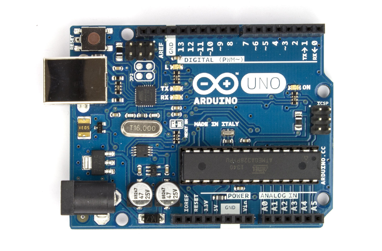
Pay special attention on the digital pins on the top... specially the ones with "~" this means that these are the PWM pins very important and very short supply, thats why we need this for PWM purposes only.

And see the lower right corner... it says "ANALOG IN" Im not sure you can use it for controlling too...

So going back to your pin assignments above...
Powerhead relay can be assigned to non pwm pins and not pin13.
Pin1 i believe cannot be used and its reserved


Let me show you what i did on mine.

Pin0 - reserved
Pin1 - reserved
Pin2 - relay1
Pin3 - Blue LED driver (PWM)
Pin4 - LCD
Pin5 - LCD (PWM)
Pin6 - LCD (PWM)
Pin7 - LCD
Pin8 - relay2
Pin9 (free PWM)
Pin10 (free PWM)
Pin11 - White LED driver (PWM)
Pin12 - LCD
Pin13 - LCD

So right now I have Pin 9 & 10, both PWM still free for other use.

Hope this helps.


.


katchupoy is offline   Reply With Quote
Unread 02/28/2012, 11:40 AM   #1269
wardda
Registered Member
 
Join Date: Feb 2010
Posts: 153
Quote:
Originally Posted by katchupoy View Post
I apologize if I am no help. I was not able to follow the more advanced sketches because they went so fast and I got left behind. Im beginning to get the itch again, maybe I will have courage to move to the next level...

I want, temp controller and maybe a PH monitor or something. Im not even sure if this is possible. I already have the PH probe, so I guess why not?
If you go for the PH probe and temp controller I would love to see it outlined here with your normal step by step attention to detail.

Thanks again for all you have done for this project.


wardda is offline   Reply With Quote
Unread 02/28/2012, 12:26 PM   #1270
katchupoy
Moved On
 
katchupoy's Avatar
 
Join Date: Feb 2003
Location: Kent, WA
Posts: 1,548
@wardda,

If you ask me concerning lights and relay, then I can help you.... just no temps and PHs for now.


katchupoy is offline   Reply With Quote
Unread 02/28/2012, 01:12 PM   #1271
Dan_Cochran
Registered Member
 
Join Date: Feb 2012
Location: Michigan
Posts: 10
Quote:
Originally Posted by wardda View Post
I am working on getting my LED controller running and I'm reading through the original katchupoy sketch listed on the google source site and I see there are a couple of relays listed ledPin1 and ledPin2. I'm assuming these are physical relays that are turning the meanwells on and off is that correct?

Dan
the physical relays 1 and 2 are my wave maker power heads.

I just checked back, and thanks for the info katchupoy.

I think i might just have it. " I also did Alot of google on how arduino code works"
I have been cleaning things up in the code that i will not be using for a while or at all.

So far relay 1 and 2 are on pin 13 and 12 "I changed them", they now are working, along with temps and the fan relay turns on, and off if temp1 or temp2 gets to hot, and shuts fans off at anything under 77

I have not adjusted clock yet to test the relay 4 for sump lights or my led drivers, but that is next.

my pins are now

pin 13 = relay 1
pin 12 = relay 2
pin 11 = led white driver
pin 3 = led blue drivers
pin 2 = open
pin 1 = temps
pin 0 = Moon //not installed on tank yet

pin A0/ 14 i did not use
Pin A1/ 15 open
Pin A2/ 16 Relay 4 for fuge/sumplight
Pin A3/ 17 Relay 3 for Fans
Pin A4 and A5/ 18 & 19 RTC

I found if I use the number 17 for a pin in-place of A3 things seam to work.

In the code I did a search and // a bunch of stuff like PH
All of that stuff i might try later but not for now, I'm too new to the code stuff.

But so far I like the scroll screen option.

One day I might play around and learn how to make a menu option for effects on demand.

I will let you know how everything works out if the other relay for sump light and Led stuff works, I have the full day to play around with it and finish things off.

here is a pic of what i have so far, sorry a little fizzy


Dan_Cochran is offline   Reply With Quote
Unread 02/28/2012, 03:32 PM   #1272
katchupoy
Moved On
 
katchupoy's Avatar
 
Join Date: Feb 2003
Location: Kent, WA
Posts: 1,548
Dan,
what pins are you using for your LCD? Thanks.


katchupoy is offline   Reply With Quote
Unread 02/28/2012, 05:14 PM   #1273
Dan_Cochran
Registered Member
 
Join Date: Feb 2012
Location: Michigan
Posts: 10
LiquidCrystal lcd(8,9,4,5,6,7);


i did not need to wire any of that lcd stuff.

across the top it said 13,12,11,3,2,1,0 open

bottom all the power pins, then No A0, but A1,A2,A3,A4,A5 open


Dan_Cochran is offline   Reply With Quote
Unread 02/28/2012, 05:41 PM   #1274
Dan_Cochran
Registered Member
 
Join Date: Feb 2012
Location: Michigan
Posts: 10
katchupoy, thanks for the idea about the loop

My temps were froze at 185 after i pluged it back in from adding more cords.

this is what i did.

PHP Code:


void loop
()
{
  
onesecond();
  
relay2();
  
relay1();
sensors.getTempFByIndex(0);  // I added this in the LOOP 
so far it works, but if it don't, i think it is on the right track


Dan_Cochran is offline   Reply With Quote
Unread 02/28/2012, 09:49 PM   #1275
Dan_Cochran
Registered Member
 
Join Date: Feb 2012
Location: Michigan
Posts: 10
katchupoy, i tried your 2 min led run threw, Post #235

everything works.

My relay and outlet box is not done yet but everything is wired up, tomorrow i should see my led's running off from my arduino.

I don't have anything mounted in my stand yet, but with any luck it should be done tomorrow.


Me and my wife was talking about a switch to bypass the pwm, but later on this week i might look into what kind of code i can find that might allow me to turn lights on 75% or something from using one of the buttons, Just in case I want lights on for a min or 2 after hours, "new frag or something I bring home at night"


For anyone just visiting this thread, There is Alot of info in these 50+ pages.
this is where I got 98% of my info. Take note's as you read them and print the how to wire pics, it will help out Alot when build time comes.
But that is just how I did it.

katchupoy, One Big Hi-Five to you! And everyone else, even the people that only asked questions " it saved me time of asking "


Dan_Cochran is offline   Reply With Quote
Reply


Posting Rules
You may not post new threads
You may not post replies
You may not post attachments
You may not edit your posts

BB code is On
Smilies are On
[IMG] code is On
HTML code is On


Similar Threads
Thread Thread Starter Forum Replies Last Post
DIY Led Build of the Month plankton99 Do It Yourself 11 11/20/2011 08:21 AM
DIY leds...now with arduino Controlled lights... António Vitor Do It Yourself 4 05/18/2011 02:13 AM
Yet Another DIY LED Build Thread csarkar001 Do It Yourself 54 05/11/2011 05:55 PM
One quick DIY LED question Impossible Do It Yourself 4 10/27/2010 09:50 AM
Anyone DIY LEDs in their Biocube? bassplaya12 Do It Yourself 13 08/15/2010 01:03 PM


All times are GMT -6. The time now is 04:32 AM.


Powered by vBulletin® Version 3.8.4
Copyright ©2000 - 2024, Jelsoft Enterprises Ltd.
Powered by Searchlight © 2024 Axivo Inc.
Use of this web site is subject to the terms and conditions described in the user agreement.
Reef CentralTM Reef Central, LLC. Copyright ©1999-2022
User Alert System provided by Advanced User Tagging v3.3.0 (Pro) - vBulletin Mods & Addons Copyright © 2024 DragonByte Technologies Ltd.