
|
|
 02/27/2013, 10:59 PM
|
#1 |
|
Registered Member
Join Date: May 2012
Location: Spring, TX
Posts: 744
|
DIY Sea Swirl Thingy-ma-jig
So this design has been done before and it's not really a secret. However, I just wanted to make a log of it on here for people that would like to make their own one day. The only problem I encountered while making these arose before I even started. The diameter of the internal pipes of the spinning component is only 1/4". I have seen others online make these and they have claimed that they can handle 500 GPH or more each. This worried me because I was thinking there was no way that a 1/4" diameter hole could handle that much flow, but the guy at Lowe's made a good point. There aren't really sprinklers with larger diameters than that. So, maybe it's not quite that much per hour (physics can be unruly at times), but I think that two of them will be plenty enough to handle my ~350 GPH return. Anyways, here are lots of pictures for your visual entertainment!
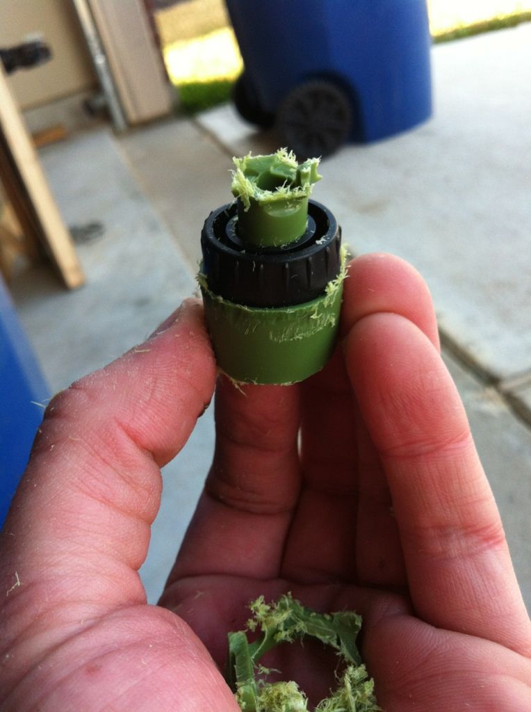
 Items needed: -3/4" PVC Coupling (slip x slip) -Cheap, PVC sprinkler from any generic place -1/2" PVC Socket Cap -1/2" 90 Degree Elbow -1/2" PVC (only need a bit) -PVC Cement -Dremel -Torch The starting product. They are available at many places. 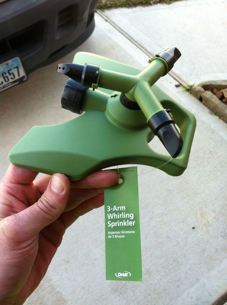 The key to this project. 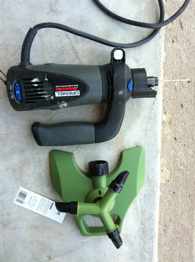 Cut off the arms. 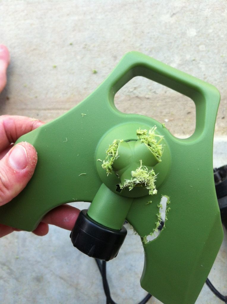 Get rid of everything but the main pipe that water goes through. 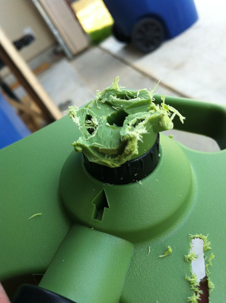 Isolate the spinning component. 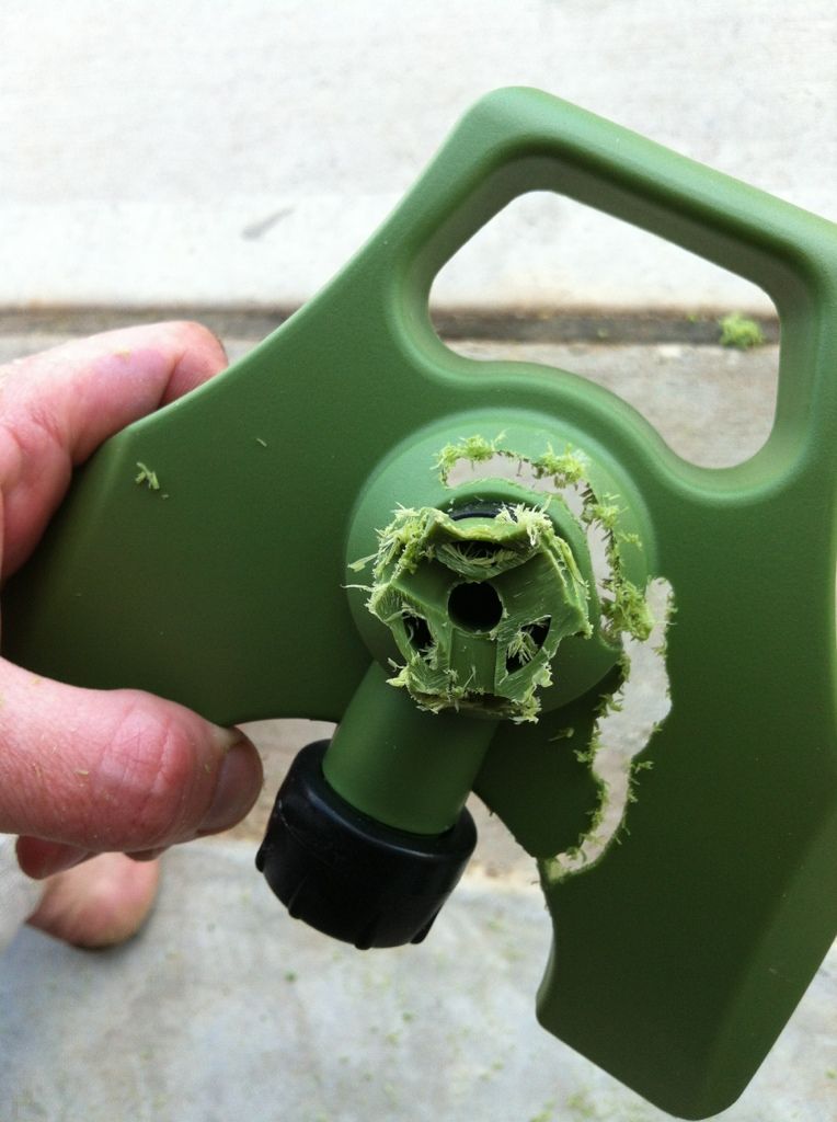 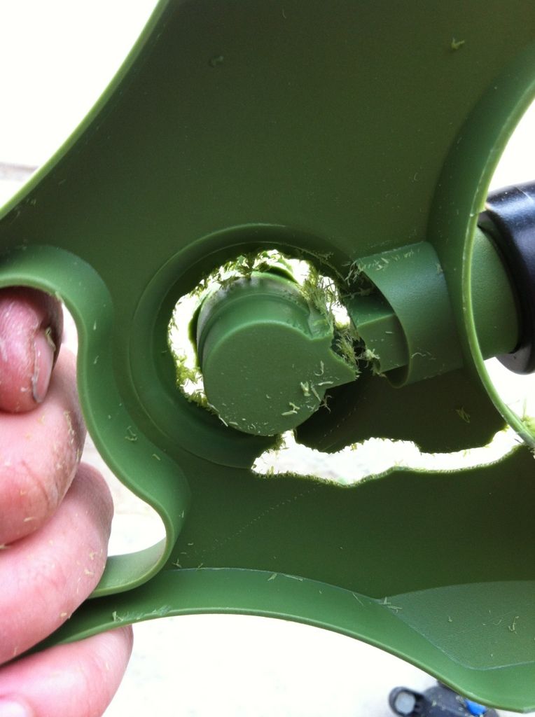 Done! Now the next step. 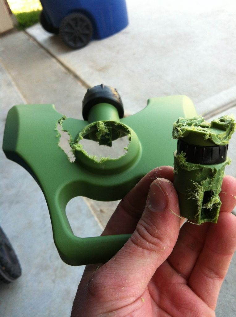 Cut off the bottom (opposite of the spinning arm side) to expose the part that water goes through. 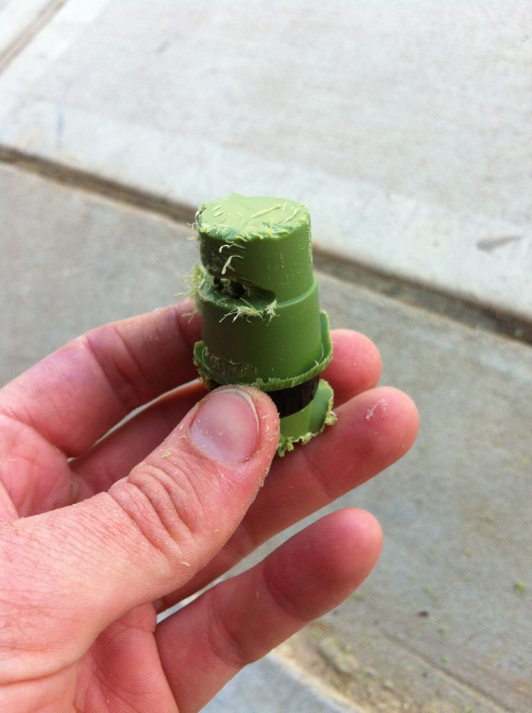 Done. 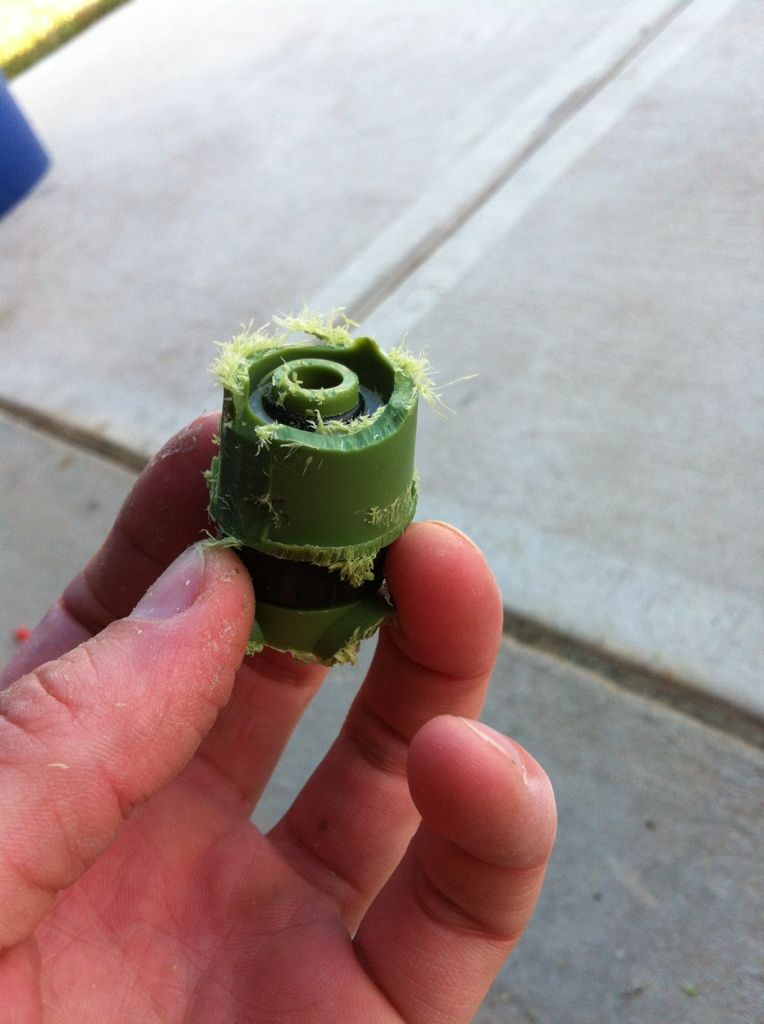
|

|

|
|
02/27/2013, 10:59 PM
|
#2 |
|
Registered Member
Join Date: May 2012
Location: Spring, TX
Posts: 744
|
Now to clean up both sides. Make sure that the fatter part (bottom part) isn't completely trimmed down like in the picture. It will make bonding to the 3/4" coupling a little more difficult because it will be too trim.
 Time to drill the 1/2" slip cap. Make sure to drill a pilot and then go in with a drill bit that matches the outside diameter of the top part of the spinning device (the one the connected to the spinning arms), or slightly smaller, and connect them. 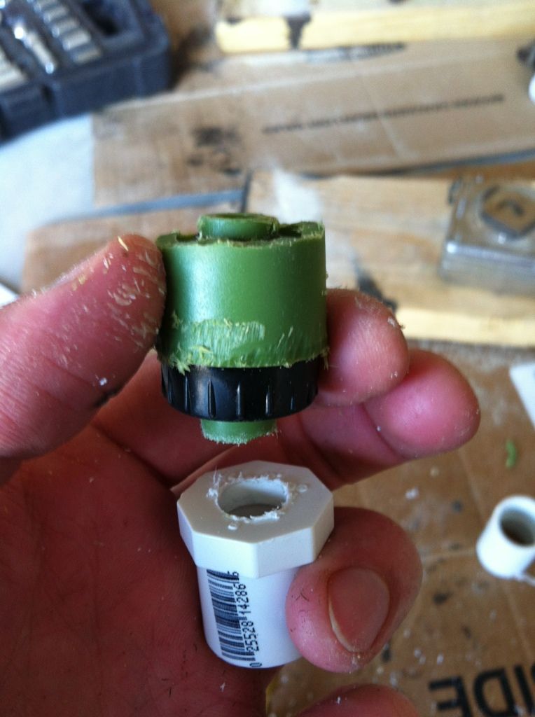 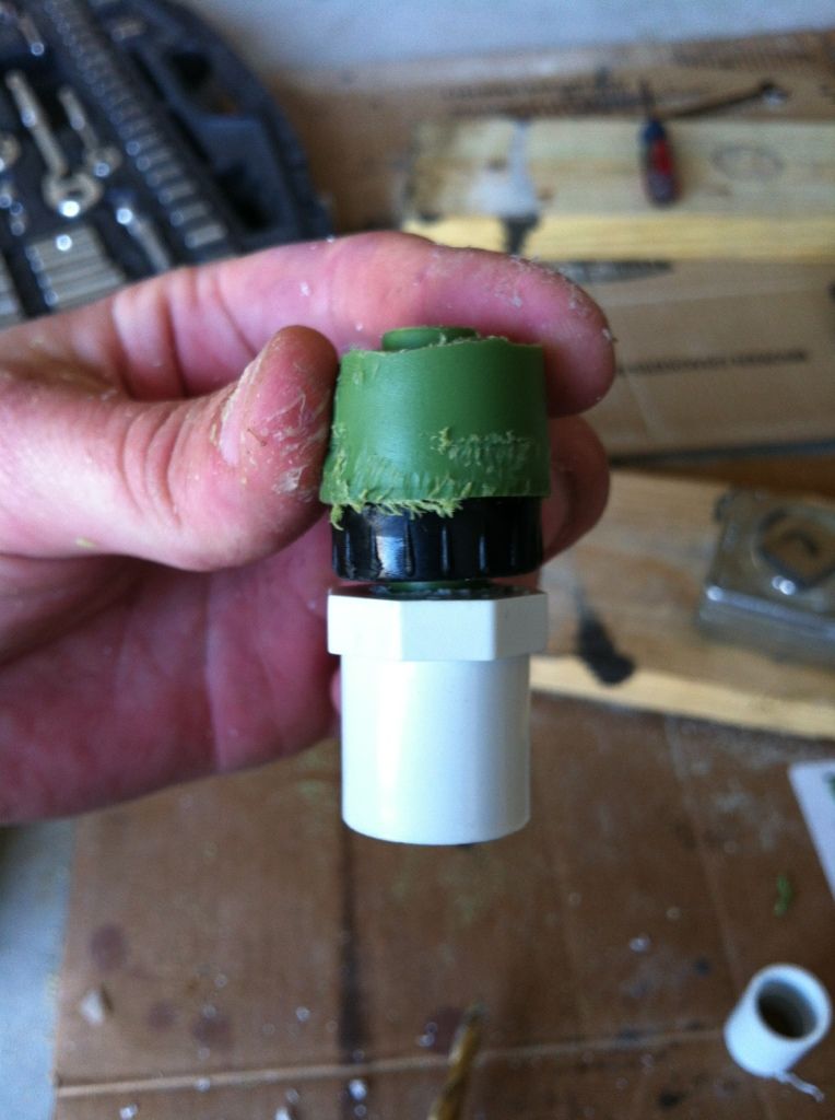 Now slide the 1/2" elbow on the 1/2" slip cap and PVC glue the 3/4" coupling to the fatter part (bottom) of the spinning component. 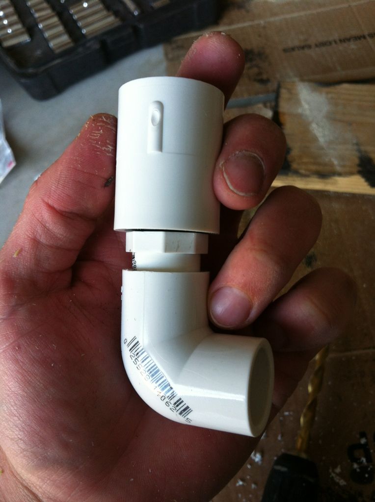 Now, it's time to make spouts out of the 1/2" PVC pipe. Gentlemen, start you torches! Just bend some PVC, cut/sand it as you like, and connect them all! 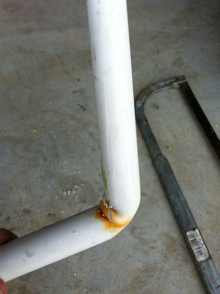 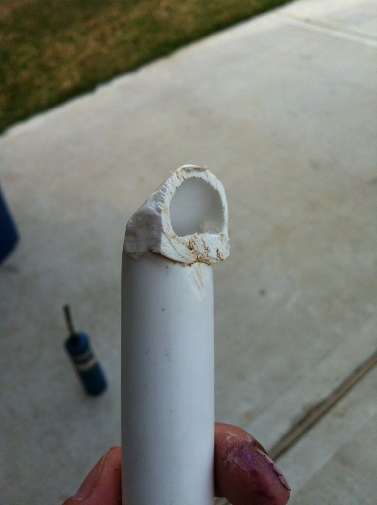 Finished product. Time to break out the Krylon and enjoy! 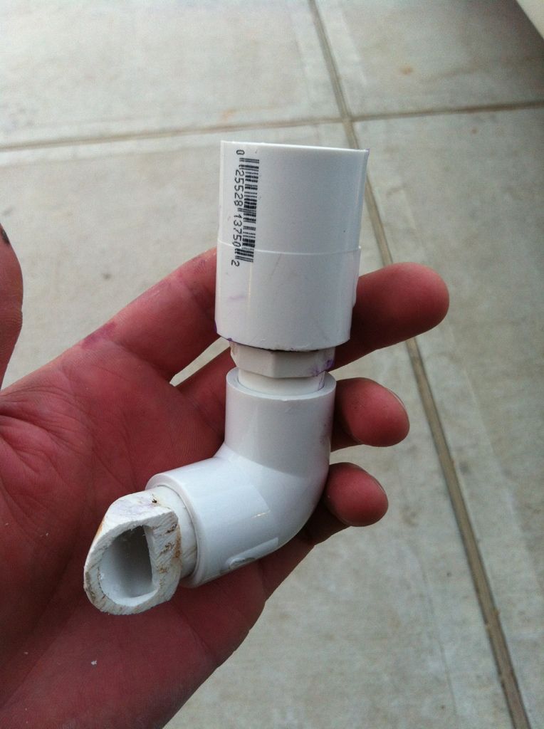
|
|
|
|
|
02/27/2013, 11:12 PM
|
#3 |
|
Not afriad to admit wrong
Join Date: Jun 2012
Location: South of WashDC in Maryland
Posts: 7,774
|
Lets see it in action.
__________________
Stock:LPS/SPS|1 hippo|4 OC Clown|4 Pepp shrimp|2 Brittle Star|3000+ Copepods|10+ MiniBrittle|8+ Bristle Worm|2 Anemone|100+ mini-feather|4 boys 14,21,22,22 Current Tank Info: Tank:300g Mixed Reef 300+lb LR|4" LS|5x MP40W|75g fuge|5x RadionPRO|RO DB250 skimmer|Apex |
|
|
|
|
02/27/2013, 11:15 PM
|
#4 |
|
Registered Member
Join Date: Dec 2010
Location: Fresno, CA
Posts: 83
|
Ok...interesting....but how does it work in the tank? Anyone have these in their tanks or have a video on YouTube to watch?
|
|
|
|
|
02/27/2013, 11:51 PM
|
#5 |
|
Registered Member
Join Date: May 2012
Location: Spring, TX
Posts: 744
|
My project has taken much longer than I expected but it's slowly coming together. I will be gluing up the external/internal overflow box tomorrow then I just have to let it cure for a bit. I'll put a video up to report the results once I have the cycle started. I have full confidence in them. If anything, I'm afraid they might spin too fast. I made the spouts short and tried to make bigger holes (which should slow down the spin a bit), but I have a pretty mean angle coming out of the spout and the component spins when you blow on it.
|
|
|
|
|
02/28/2013, 01:00 AM
|
#6 |
|
Registered Member
 Join Date: Oct 2012
Location: Australia
Posts: 3,907
|
If it spins too fast a small hole drilled on the back of the arm should slow it down, bit like a siphon break hole if you know what i mean. You can always enlarge the back hole until you're happy with the spin rate. Looks good so far, thanks for the pics

__________________
Andrew |
|
|
|
|
02/28/2013, 01:42 AM
|
#7 | ||
|
Registered Member
Join Date: May 2012
Location: Spring, TX
Posts: 744
|
Quote:
Quote:
https://www.youtube.com/watch?v=D3iv39VA0ws After that trial run I don't think it's going to spin too fast. I think that between however many it takes to handle the return pump (two, maybe three), they are going to spin at a nice rate and get a lot of turbulent flow. I'm excited to get them up and running once my internal/external are completed. Last edited by crn005; 02/28/2013 at 01:49 AM. |
||
|
|
|
|
02/28/2013, 05:11 AM
|
#8 |
|
Registered Member
Join Date: Oct 2012
Posts: 88
|
ingenious! Will try this one out! My only concern would be that algae or detritus build up over time would hinder or stop movement completely.
|
|
|
|
|
02/28/2013, 08:05 AM
|
#9 |
|
Registered Member
Join Date: Oct 2012
Location: CT
Posts: 670
|
THATS GREAt. i would have never ever thought of that. Good DIY. I had to read it with the title you had on it.
|
|
|
|
|
02/28/2013, 02:44 PM
|
#10 |
|
Registered Member
Join Date: May 2012
Location: Spring, TX
Posts: 744
|
I don't think the algae will be much of a problem. You can push the spinning component pretty far down into the 1/2" cap to where the spinning part is almost entirely concealed. Plus, I'm just dry fitting them to the return so I can remove them and take a toothbrush to it with ease. The best part about these guys is that they cost about $5 or less to make if you have PVC glue and 1/2" or 3/4" PVC lying around. It doesn't take much. Plus, you're looking at a 30-45 minute build time for each, depending on how fast you work.
|
|
|
|
|
02/28/2013, 03:13 PM
|
#11 |
|
Registered Member
Join Date: Dec 2012
Posts: 103
|
I am definitely looking forward to a video of this working.
|
|
|
|
|
02/28/2013, 05:36 PM
|
#12 |
|
Registered Member
Join Date: May 2012
Location: Spring, TX
Posts: 744
|
Just as soon as I get my external and internal overflow boxes up and running, I will definitely post a video of them in action on the display tank. Feel free to expedite the process on this other thread so I can deliver on this one!
http://www.reefcentral.com/forums/sh...2261673&page=3 |
|
|
|
|
03/12/2013, 02:36 PM
|
#13 |
|
Registered Member
Join Date: Feb 2013
Posts: 15
|
Been following this
Ok I am in the planning stages of my tank and I am a DIY kind of guy. So much so that I would probably pay more to build it myself than buy it
 . I am going to shoot for between 500-600 GPH (actual) from my return. In your testing what do you feel one of these puts out. I am thinking one swirl in the center of my 100L and then two 1/2" loc-line nozzles in the front corners should do the trick. . I am going to shoot for between 500-600 GPH (actual) from my return. In your testing what do you feel one of these puts out. I am thinking one swirl in the center of my 100L and then two 1/2" loc-line nozzles in the front corners should do the trick.
|
|
|
|
|
05/08/2013, 12:15 PM
|
#14 |
|
Registered Member
Join Date: May 2012
Location: Spring, TX
Posts: 744
|
Sorry I'm so late to reply! I didn't realize You had commented. Anyways, I think that should be fine. They seem to restrict the flow a little more than just running a lock line but they definitely can move some water.
My build has been slowed down quite a bit due to money and time (story of my life) but its getting close to being up and running. I just tried a little dry fitting trial run with two of them connected to a pipe running across the front of my internal overflow. I'm going to give them a go real soon and see how both in action at the same time work. However, I'm only doing this to test their abilities. I will not be using them permanently due to how small my tank is. I feel like the pipe and rotating hands will right under my LEDs and it will cast annoying shadows. We will see but they're probably not going to be used until I do my next bigger build  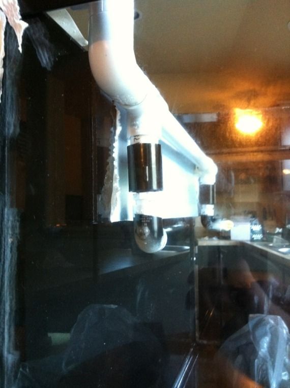 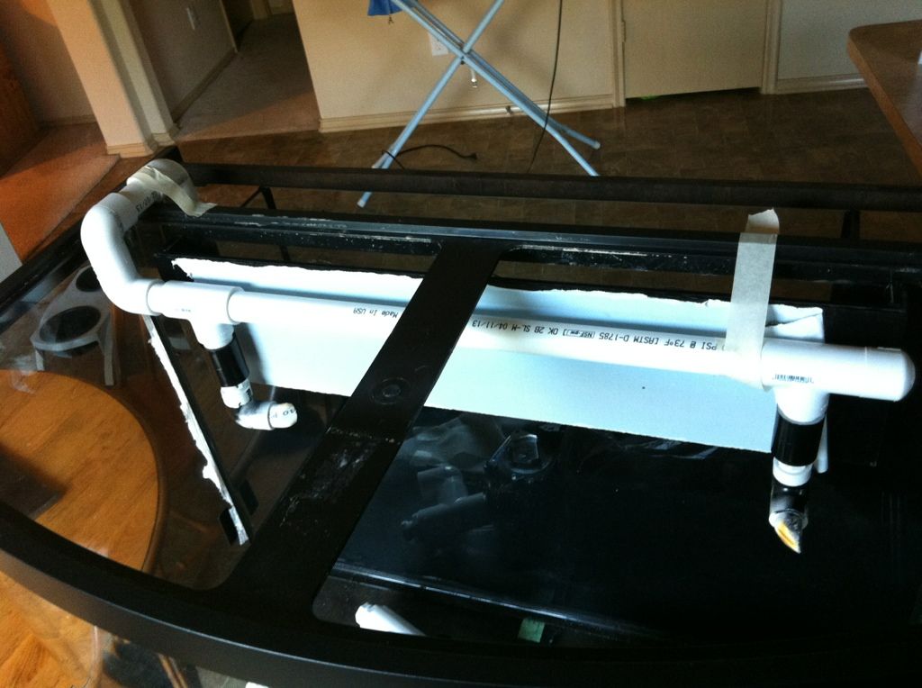 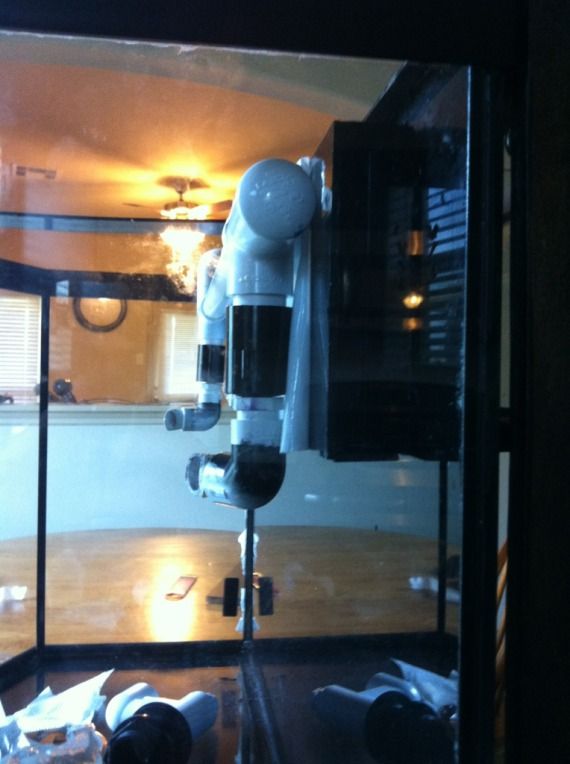
Last edited by crn005; 05/08/2013 at 12:21 PM. |
|
|
|
 |
|
|


